Blanking mechanism

A blanking and strip-shaped technology, applied in the direction of feeding device, positioning device, storage device, etc., can solve the problems of low work efficiency, achieve the effect of improving work efficiency, avoiding manual cutting, and improving the degree of automation

Pending Publication Date: 2022-03-15
深圳市山柏智能设备有限公司
View PDF0 Cites 0 Cited by
  • Summary
  • Abstract
  • Description
  • Claims
  • Application Information

AI Technical Summary

Problems solved by technology

However, the traditional method of cutting the convex part of the strip-shaped materi

Method used


Image

  • Blanking mechanism
  • Blanking mechanism
  • Blanking mechanism

Examples


Embodiment Construction

[0027] The following will clearly and completely describe the technical solutions in the embodiments of the present invention with reference to the accompanying drawings in the embodiments of the present invention. Obviously, the described embodiments are only part of the embodiments of the present invention, not all of them. Based on the embodiments of the present invention, all other embodiments obtained by persons of ordinary skill in the art without creative efforts fall within the protection scope of the present invention.

[0028] It should be noted that if there is a directional indication (such as up, down, left, right, front, back...) in the embodiment of the present invention, the directional indication is only used to explain the position in a certain posture (as shown in the accompanying drawing). If the specific posture changes, the directional indication will also change accordingly.

[0029] In addition, if there are descriptions involving "first", "second" and ...


PUM


Abstract

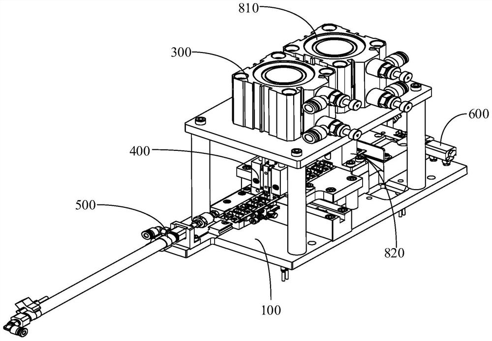
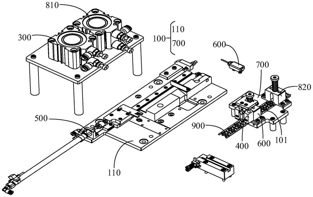
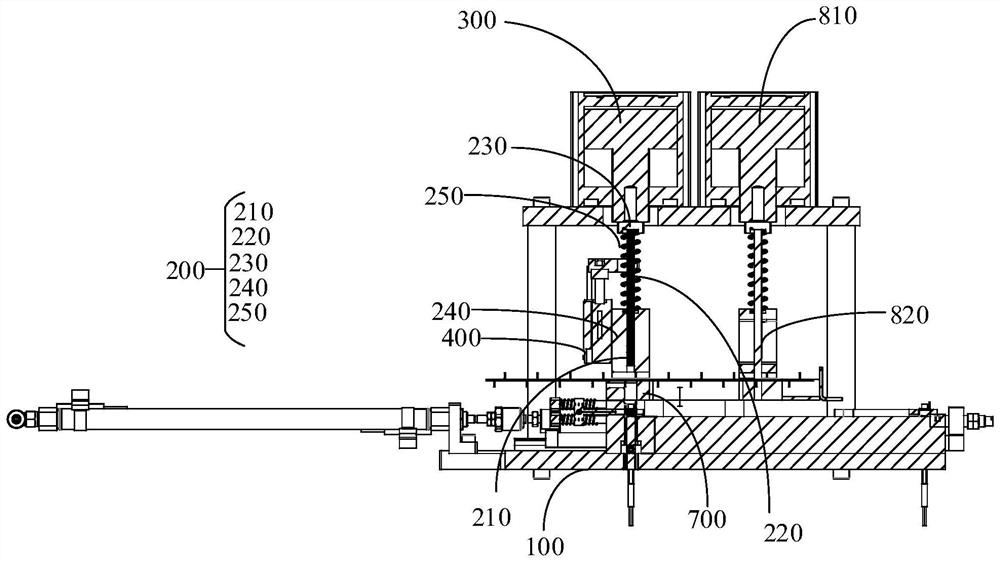
The blanking mechanism is used for blanking strip-shaped materials, the blanking mechanism comprises a mounting table, a cutting assembly and a first driving device, the mounting table is provided with a containing groove in the length direction of the mounting table, and the containing groove is used for containing the strip-shaped materials; the cutting assembly is mounted on the mounting table in a manner of moving up and down, and is used for cutting the convex part of the strip-shaped material; the first driving device is mounted on the mounting table and used for driving the cutting assembly to move up and down. According to the technical scheme, the production efficiency of shearing the strip-shaped materials is improved.

Description

technical field [0001] The invention relates to the technical field of powder metallurgy, in particular to a punching mechanism. Background technique [0002] In the related technology, for the processing of small parts, it is generally rolled and formed on a strip-shaped material, and then sheared. The strip-shaped blank includes two connecting parts and two extending from the connecting parts. There are two convex parts, wherein the two convex parts are located between the two connecting parts, and the two connecting parts are connected to each other; the convex parts are products for further processing and need to be cut off. However, the traditional method of cutting the convex part of the strip-shaped material is generally cut by the staff using rubber pliers, resulting in low work efficiency. Contents of the invention [0003] The main purpose of the present invention is to propose a punching mechanism, aiming to provide a new punching mechanism to improve the produ...

Claims


Application Information

Patent Timeline
IPC IPC(8): B21D28/04B21D28/02B21D45/02B21D43/00
CPCB21D28/04B21D28/02B21D45/02B21D43/003
Inventor 罗木华
Owner 深圳市山柏智能设备有限公司
Why Eureka
Try Eureka