Adjustable clamp based on aviation part machining

A component and shape adjustment technology, which is applied in the field of aviation parts processing, can solve the problems of poor clamping effect of aviation special-shaped plates, reduced machining accuracy, offset or falling off of aviation plates, etc., so as to facilitate high-strength processing and improve effective Clamping area, the effect of increasing the clamping area

Active Publication Date: 2022-03-15
四川旭博精密科技有限公司
View PDF9 Cites 3 Cited by
  • Summary
  • Abstract
  • Description
  • Claims
  • Application Information

AI Technical Summary

Problems solved by technology

[0002] With the development of society, the aviation industry is also progressing by leaps and bounds. The development of aviation has greatly changed the structure of transportation. Airplanes provide people with a fast, convenient, economical, safe and comfortable means of transportation, and become the means of intercontinental travel for people. The main tool has closely connected the exchanges of countries all over the world; in the aviation parts, most of the plate parts are processed, such as the shell plate, the wing plate, etc., because the flight design requires that the shape of the aviation shell is basically streamlined, That is, the casing plate is composed of a number of special-shaped plates with curved surfaces. Due to the special type of aviation plate, the fixture needs to have strong adaptability and adjustment ability, and can adjust the clamping form to adapt to the shape of the plate. Now Some fixtures cannot be adaptively adjusted according to the shape of the board, resulting in poor clamping effect and unstable clamping of aviation special-shaped boards, and it is easy to cause the board to shift or fall off during processing, especially when cutting , grinding and other processing procedures that will generate large vibrations, thereby reducing the processing accuracy of aviation panels

Method used


Image

  • Adjustable clamp based on aviation part machining
  • Adjustable clamp based on aviation part machining
  • Adjustable clamp based on aviation part machining

Examples


Embodiment 1

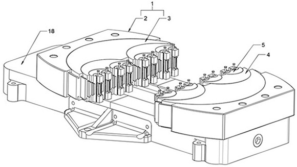
[0028] Embodiment one, as figure 1 and figure 2 As shown, an adjustable fixture based on aviation parts processing includes two sets of clamping mechanisms 1 symmetrically arranged, and the two sets of clamping mechanisms 1 can move relative to each other to form a clamping space; the clamping mechanism 1 includes The base 2 and the first clamping block 3, the first clamping block 3 is slidably arranged on the base 2, and a plurality of second clamping blocks 4 are slidably arranged on the first clamping block 3 along its own radial direction, the first clamping block 3 The sliding paths of the second clamping block 4 and the second clamping block 4 are both arc-shaped, and the two sets of clamping mechanisms 1 are used to adapt to clamping parts of different shapes through the arc deflection of the first clamping block 3 and the second clamping block 4; the clamping mechanism 1 It is a multi-level fixture, including several levels of clamping blocks, that is, the first clam...

Embodiment 2

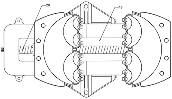
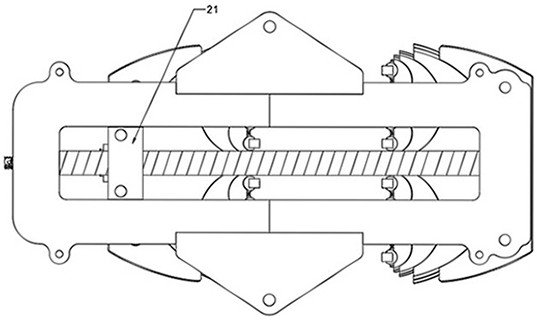
[0030]Embodiment 2. Embodiment 1 provides a clamp that can adapt to the clamping of special-shaped plates. Although the clamping area is improved by adapting to the shape of the part, the clamping strength of the special-shaped part is improved compared with the ordinary clamp, but only through the symmetrical The set clamping part 6 restricts the movement of the part, which is equivalent to restricting the left and right movement of the part. The limit direction of the part is relatively small. After the aviation parts are clamped, two processes of processing and testing are required. The processing includes grinding, cutting, drilling Holes, etc., its strength is relatively large, and the detection of cracks, roughness, etc. is detected by optical instruments, and its strength is relatively small. The clamping strength of the fixture in Example 1 meets the strength required for detection, but it is difficult to meet the strength of processing with high strength. process, in t...

Embodiment 3

[0031] Embodiment three, as Figure 6 to Figure 8 As shown, the shapes of the first clamping block 3, the second clamping block 4 and the third clamping block 5 are all semicircular, and the shapes of the first clamping block 3, the second clamping block 4, the third clamping block 5 and the arc-shaped main body 7 The arc-shaped ends are all provided with arc-shaped slide rails 13, and the base 2, the first clamp block 3, the second clamp block 4 and the third clamp block 5 are all provided with arc-shaped slide grooves 14, and the arc-shaped slide rails 13 and arc-shaped The cross-sectional shape of the chute 14 is "T" shape, and the arc-shaped slide rail 13 on the first clamping block 3 is adapted to the arc-shaped chute 14 on the base 2, so that the first clamping block 3 moves along its own The trajectory of the arc-shaped slide rail 13 is arc-shaped deflection, and the arc-shaped slide rail 13 on the second clamping block 4 is adapted to the arc-shaped slide groove 14 on ...


PUM


Abstract

The invention discloses an adjustable clamp based on aeronautical part machining, and relates to the field of aeronautical part machining, the adjustable clamp comprises two sets of symmetrically arranged clamping mechanisms, and the two sets of clamping mechanisms can move relatively to form a clamping space; the clamping mechanism comprises a base and a first clamping block, the first clamping block is arranged on the base in a sliding mode, a plurality of second clamping blocks are arranged on the first clamping block in the radial direction of the first clamping block in a sliding mode, and the sliding paths of the first clamping block and the second clamping blocks are both in an arc shape. The two sets of clamping mechanisms are used for clamping parts in different shapes through arc-shaped deflection of the first clamping blocks and the second clamping blocks. A clamping space is formed between the two sets of clamping mechanisms, and the shape of the clamping space can be adaptively adjusted according to the shape of a part, so that the clamping area is increased, the clamping strength is improved, the part is clamped more stably, and high-strength machining of the part is facilitated.

Description

technical field [0001] The invention relates to the field of aviation parts processing, in particular to an adjustable fixture based on the processing of aviation parts. Background technique [0002] With the development of society, the aviation industry is also progressing by leaps and bounds. The development of aviation has greatly changed the structure of transportation. Airplanes provide people with a fast, convenient, economical, safe and comfortable means of transportation, and become the means of intercontinental travel for people. The main tool has closely connected the exchanges of countries all over the world; in the aviation parts, most of the plate parts are processed, such as the shell plate, the wing plate, etc., because the flight design requires that the shape of the aviation shell is basically streamlined, That is, the casing plate is composed of a number of special-shaped plates with curved surfaces. Due to the special type of aviation plate, the fixture ne...

Claims


Application Information

Patent Timeline
Patent Type & Authority Applications(China)
IPC IPC(8): B23Q3/06B24B41/06B25B11/00
CPCB23Q3/062B24B41/06B25B11/00
Inventor 马强张云洲
Owner 四川旭博精密科技有限公司
Why Eureka
Try Eureka