Clamping device for linear motor machining
A clamping device and linear motor technology, applied in the direction of workbench, manufacturing tools, etc., can solve the problems of poor stability of positioning tooling, inability to clamp in multiple directions, single clamping of the clamping device, etc., to avoid compression damage, clamping Good holding effect, avoid sliding effect
- Summary
- Abstract
- Description
- Claims
- Application Information
AI Technical Summary
Problems solved by technology
Method used
Image
Examples
Embodiment 1
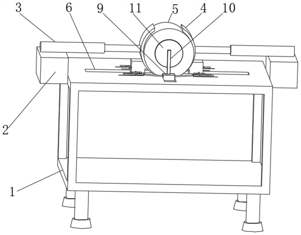
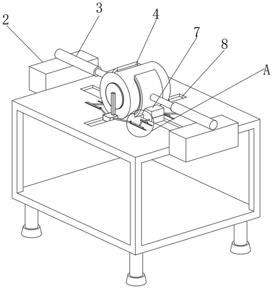
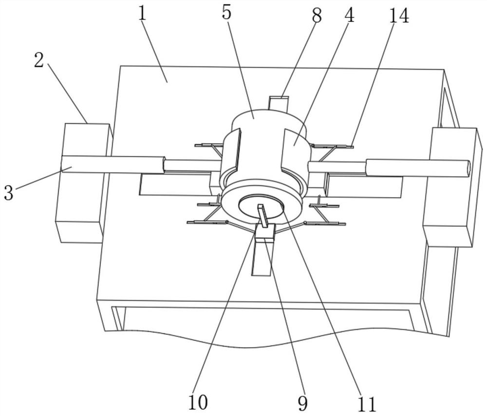
[0028] see Figure 1-5 , the present invention provides a technical solution: a clamping device for linear motor processing, including a frame 1, a support column is fixedly connected to the bottom outer wall of the frame 1, a support block 2 is fixedly connected to the top outer wall of the frame 1, and the support The top outer wall of the block 2 is fixedly connected with a cylinder 3, and one end of the cylinder 3 is fixedly connected with a clamping device 4, the top outer wall of the frame 1 is provided with a motor 5 between the clamping devices 4, and the top outer wall of the frame 1 is provided with The first chute 6, the inner wall of the first chute 6 is slidably connected with the first slider 7, the top outer wall of the frame 1 is provided with the second chute 8, the first chute 6 and the second chute 8 are all arranged on Both sides of the motor 5, and the first chute 6 and the second chute 8 are arranged vertically.
[0029] In this embodiment, the motor 5 i...
Embodiment 2
[0031] see Figure 1-5 As shown, on the basis of Embodiment 1, the present invention provides a technical solution: the inner wall of the second chute 8 is slidably connected with the second slider 9, and the top outer wall of the second slider 9 is fixedly connected with the limit rod 10, One side outer wall of the limit rod 10 is fixedly connected with the limit block 11, one side outer wall of the first slider 7 is movably connected with a first connecting rod 12, and one end of the first connecting rod 12 away from the first slider 7 is movably connected with a second A movable bar 13, the top outer wall of frame 1 is provided with the 3rd chute 14, the inwall of the 3rd chute 14 is slidably connected with the 3rd slider 15, the top outer wall of the 3rd slider 15 and the first movable bar 13 The outer wall of the bottom is fixedly connected, and the outer wall of the first movable rod 13 away from the first connecting rod 12 is movably connected with a second connecting r...
Embodiment 3
[0034] see Figure 6-7 As shown, on the basis of Embodiment 1 and Embodiment 2, the present invention provides a technical solution: the clamping device 4 includes a clamping block 401, the inner wall of one side of the clamping block 401 is fixedly connected with an air bag 402, and the first slide The inner wall of the block 7 is fixedly connected with an air pump, the inner wall of the air pump is fixedly connected with a connecting pipe 403, and the end of the connecting pipe 403 away from the air pump is fixedly connected with the inner wall of the air bag 402, and the upper and lower outer walls of the clamping block 401 are fixedly connected with a mounting block 404 The outer wall of the mounting block 404 is provided with a movable groove 405, the inner wall of the movable groove 405 is slidingly connected with a rubber pad 406, and the outer wall of the rubber pad 406 away from the airbag 402 is fixedly connected with a clamping block 407, and the outer wall of the mo...
PUM
 Abstract
Description
Claims
Application Information
 - R&D
- Intellectual Property
- Life Sciences
- Materials
- Tech Scout
- Unparalleled Data Quality
- Higher Quality Content
- 60% Fewer Hallucinations
Browse by: Latest US Patents, China's latest patents, Technical Efficacy Thesaurus, Application Domain, Technology Topic, Popular Technical Reports.
© 2025 PatSnap. All rights reserved.Legal|Privacy policy|Modern Slavery Act Transparency Statement|Sitemap|About US| Contact US: help@patsnap.com


