Automatic blanking mechanism for section pipes

An automatic cutting and pipe technology, applied in the direction of conveyors, conveyor objects, transportation and packaging, etc., can solve the problems of inability to adjust the height or angle of the cutting mechanism, inconvenient for metal pipe cutting, etc., and achieve convenient cutting work. Effect

Inactive Publication Date: 2022-03-15
佛山市明州智能设备有限公司
View PDF0 Cites 0 Cited by
  • Summary
  • Abstract
  • Description
  • Claims
  • Application Information

AI Technical Summary

Problems solved by technology

[0004] The purpose of the present invention is to provide an automatic cutting mechanism for profiled pipes to solve the inconvenience of cutting metal pipes of different types or shapes in the above background technology. Secondly, it is not possible to adjust the height or angle of the cutting mechanism The problem of making adjustments

Method used


Image

  • Automatic blanking mechanism for section pipes
  • Automatic blanking mechanism for section pipes
  • Automatic blanking mechanism for section pipes

Examples


Embodiment Construction

[0022] The following will clearly and completely describe the technical solutions in the embodiments of the present invention with reference to the accompanying drawings in the embodiments of the present invention. Obviously, the described embodiments are only some, not all, embodiments of the present invention. Based on the embodiments of the present invention, all other embodiments obtained by persons of ordinary skill in the art without making creative efforts belong to the protection scope of the present invention.

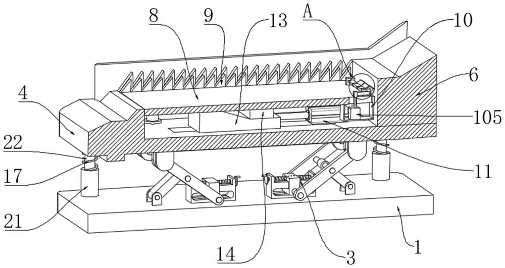
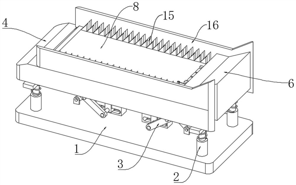
[0023] The present invention provides such as Figure 1-5 The automatic cutting mechanism for profiles and pipes shown includes a base 1 and a fixed plate 4, the fixed plate 4 is located above the base 1, a buffer assembly 2 and an angle adjustment assembly 3 are respectively installed on the top outer wall of the base 1, and the buffer assembly 2 is located outside the angle adjustment component 3, the height and angle of the fixed plate 4 can be easily adjus...


PUM


Abstract

The automatic discharging mechanism comprises a base and a fixing plate, the fixing plate is located above the base, a buffering assembly and an angle adjusting assembly are installed on the outer wall of the top of the base, the buffering assembly is located on the outer side of the angle adjusting assembly, and the fixing plate is connected with the base through the buffering assembly and the angle adjusting assembly. A first sleeve, a discharging table and a first air cylinder are mounted on the outer wall of the top of the fixing plate, the first sleeve is located on one side of the discharging table, the first air cylinder is located in the middle of the first sleeve, a first connecting rod is arranged in the first sleeve, and a mounting plate is mounted at one end of the first connecting rod. Through the arrangement of a first sleeve, a first connecting rod, a mounting plate, a first toothed plate, a first air cylinder, a first sliding groove, a moving plate, a first connecting plate and a second toothed plate, metal pipes of different models or different shapes can be blanked, and therefore machining or transportation of the metal pipes cannot be affected.

Description

technical field [0001] The invention relates to the technical field of profile pipes, in particular to an automatic feeding mechanism for profile pipes. Background technique [0002] Pipe is the material used to make pipe fittings. Different pipes use different pipes. The quality of pipes directly determines the quality of pipes. Construction projects, power plants, chemical plants, etc. often use this type of pipe. At the same time, pipes are also necessary materials for construction projects. [0003] When the current metal pipes are cut or polished, in order to speed up the processing speed and efficiency, the feeding mechanism and the unloading structure are generally used. However, the current unloading mechanism is inconvenient to use for different models. Or metal pipes of different shapes are blanked, and secondly, the height or angle of the blanking mechanism cannot be adjusted, which will affect the processing or transportation of metal pipes. Therefore, an automat...

Claims


Application Information

Patent Timeline
Patent Type & Authority Applications(China)
IPC IPC(8): B65G41/00B65G47/74
CPCB65G41/005B65G47/74B65G2201/0276
Inventor 刘宗明
Owner 佛山市明州智能设备有限公司
Why Eureka
Try Eureka