Combustion chamber of solid fuel internal combustion engine
A technology of solid fuel and internal combustion engine, applied in the field of combustion chamber, can solve the problems of cylinder wear and poor flow performance of solid fuel, and achieve the effect of improving thermal efficiency
- Summary
- Abstract
- Description
- Claims
- Application Information
AI Technical Summary
Problems solved by technology
Method used
Image
Examples
Embodiment 1
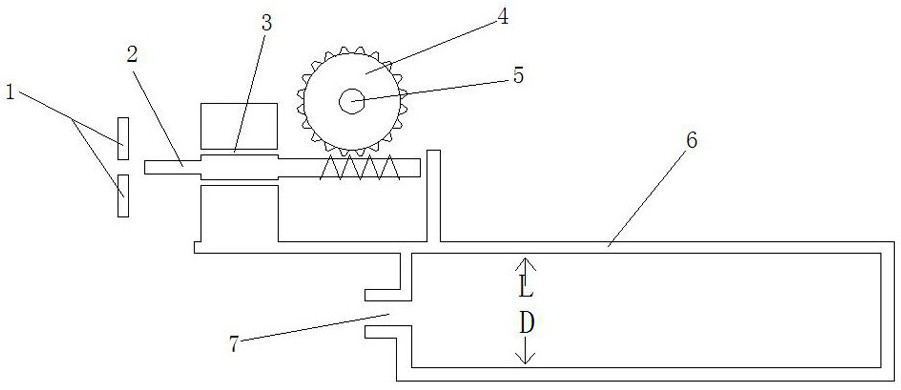
[0041] Embodiment one, such as Figures 1 to 4 , there is an air inlet 7, a feed port 20 and an air outlet 35 on the housing 6, the air enters the housing 6 from the air inlet 7, the solid fuel enters the housing 6 from the feed port 20, and the gas enters from the outlet The air port 35 is discharged, and a round hole 3 is processed in the housing 6. The worm 2 passes through the round hole 3 and the round hole on the shaft baffle 1. The worm 2 can rotate, and the shaft baffle 1 is processed with a round hole. structured as Figure 12 , the worm 2 passing through the round hole 3 does not affect the rotation of the worm 2, the shaft baffle 1 is drilled with a light hole, and the casing 6 has a threaded hole, and the shaft baffle 1 is connected to the casing 6 with bolts, or the shaft baffle The plate 1 is welded on the casing 6, the shaft baffle 1 blocks the axial movement of the worm 2 and the casing also blocks the axial movement of the worm 2, the worm 2 drives the worm w...
Embodiment 2
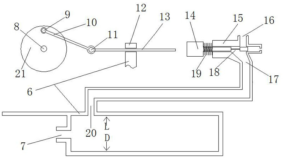
[0050] Embodiment two, such as Figures 5 to 8 , there is an air inlet 53, a feed port 54 and an air outlet 69 on the housing 52, the air enters the housing 52 from the air inlet 53, the solid fuel enters the housing 52 from the feed port 54, and the gas enters from the outlet The air port 69 is discharged, and a round hole 74 is processed in the housing 52. The worm 73 passes through the round hole 74 and the round hole on the shaft baffle 72. The worm 73 can rotate, and the shaft baffle 72 is processed with a round hole. structured as Figure 12 , the worm 73 passing through the round hole 74 does not affect the rotation of the worm 73, the shaft baffle 72 is drilled with a light hole, the housing 52 has a threaded hole, the shaft baffle 72 is connected to the housing 52 with bolts, or the shaft baffle The plate 72 is welded on the housing 52. The shaft baffle 72 blocks the axial movement of the worm 73 and also prevents the axial movement of the worm 73. The worm 73 drives...
Embodiment 3
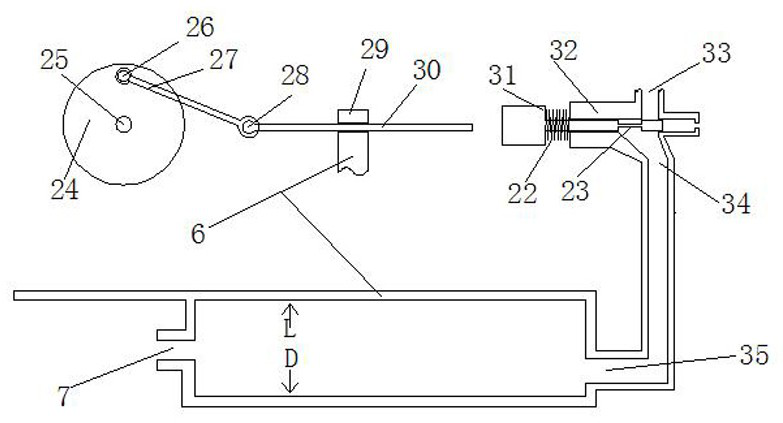
[0057] Embodiment three, such as Figures 14 to 17 , there is an air inlet 102, a feed inlet 101 and an air outlet 103 on the housing 90, air enters the housing 90 from the air inlet 102, solid fuel enters the housing 90 from the feed inlet 101, and gas enters from the outlet The air port 103 is discharged, and a round hole 114 is processed in the housing 90. The worm 91 passes through the round hole 114 and the round hole on the shaft baffle 113. The worm 91 can rotate, and the shaft baffle 113 is processed with a round hole. structured as Figure 12 , the worm 91 passing through the round hole 114 does not affect the rotation of the worm 91, the shaft baffle 113 is drilled with a light hole, and the housing 90 has threaded holes, the shaft baffle 113 is connected to the housing 90 with bolts, or the shaft baffle The plate 113 is welded on the housing 90, the shaft baffle 113 blocks the axial movement of the worm 91 and also prevents the axial movement of the worm 91, the wo...
PUM
 Abstract
Description
Claims
Application Information
 - R&D
- Intellectual Property
- Life Sciences
- Materials
- Tech Scout
- Unparalleled Data Quality
- Higher Quality Content
- 60% Fewer Hallucinations
Browse by: Latest US Patents, China's latest patents, Technical Efficacy Thesaurus, Application Domain, Technology Topic, Popular Technical Reports.
© 2025 PatSnap. All rights reserved.Legal|Privacy policy|Modern Slavery Act Transparency Statement|Sitemap|About US| Contact US: help@patsnap.com


