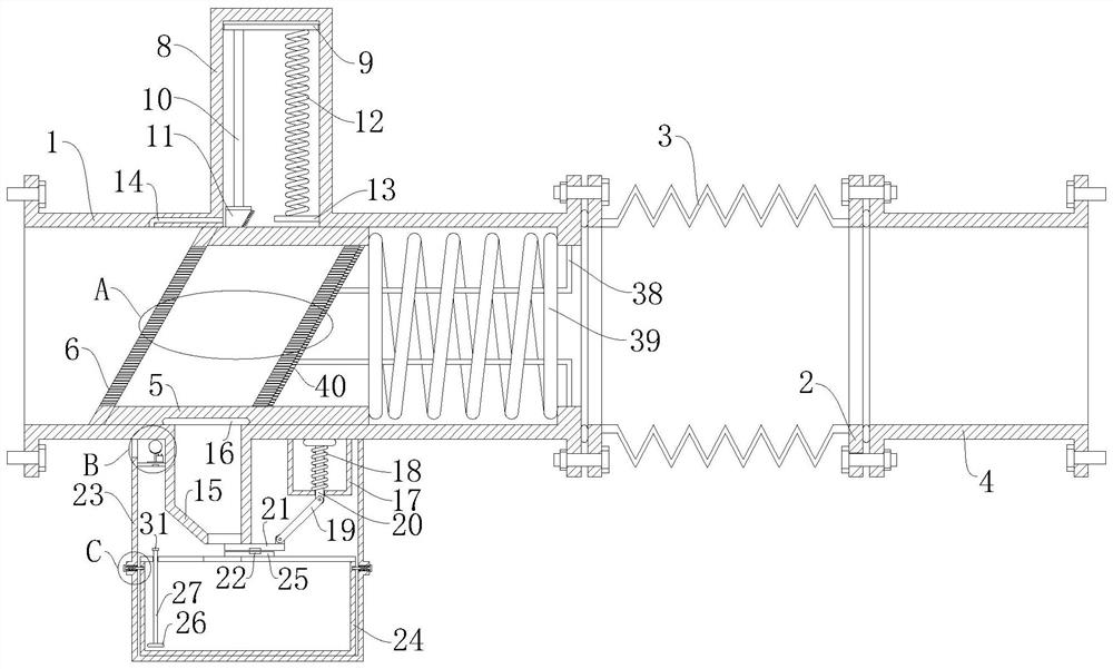
Universal joint communicating pipe
A technology of Unicom pipes and universal joints, applied in the field of Unicom pipes, can solve problems such as falling to the bottom, unusable, and blocked water flow, so as to improve work efficiency, improve water flow effects, and prevent blockages
- Summary
- Abstract
- Description
- Claims
- Application Information
AI Technical Summary
Problems solved by technology
Method used
Image

Examples
Embodiment Construction
[0031]The following will clearly and completely describe the technical solutions in the embodiments of the present invention with reference to the accompanying drawings in the embodiments of the present invention. Obviously, the described embodiments are only some, not all, embodiments of the present invention. Based on the embodiments of the present invention, all other embodiments obtained by persons of ordinary skill in the art without making creative efforts belong to the protection scope of the present invention.
[0032] In describing the present invention, it is to be understood that the terms "center", "longitudinal", "transverse", "length", "width", "thickness", "upper", "lower", "front", " Back", "Left", "Right", "Straight", "Horizontal", "Top", "Bottom", "Inner", "Outer", "Clockwise", "Counterclockwise", etc. or The positional relationship is based on the orientation or positional relationship shown in the drawings, which is only for the convenience of describing th...
PUM
 Abstract
Description
Claims
Application Information
PatSnap Eureka turns technology decisions into work you can execute. Powered by our Innovation Knowledge Graph, it runs expert workflows across engineering, life sciences, materials and intellectual property. Get your review-ready output in minutes.


