Nuclear power station wafer butterfly valve on-site pressing tool and pressing system

A technology for wafer butterfly valves and nuclear power plants, which can solve the problem of easily damaged flange sealing surfaces and valve seats and large-diameter valves by detecting the appearance of fluid at the leakage point, measuring the increase and decrease rate of the fluid, and measuring devices. Inconvenient transportation, damage to equipment and personnel, etc., to achieve the effect of effectiveness and practicability, convenient suppression, and high availability

Pending Publication Date: 2022-03-15
CLP CHINA NUCLEAR POWER ENG TECH
View PDF0 Cites 0 Cited by
  • Summary
  • Abstract
  • Description
  • Claims
  • Application Information

AI Technical Summary

Problems solved by technology

In the process of dismantling and overhauling, the existing overhaul method is to transport the valve back from the site, and clamp and press it through the valve universal pressing table, which has the following disadvantages: 1. Limited by the size of the pressing table, only small-diameter valves can be pressed ;2. It is very inconvenient to suppress. If it is a soft seal, it is easy to damage the flange sealing surface and valve seat; 3. It is inconvenient to transport large-diameter valves, and there is a risk of damage to equipment and personnel

Method used


Image

  • Nuclear power station wafer butterfly valve on-site pressing tool and pressing system
  • Nuclear power station wafer butterfly valve on-site pressing tool and pressing system
  • Nuclear power station wafer butterfly valve on-site pressing tool and pressing system

Examples


Embodiment 1

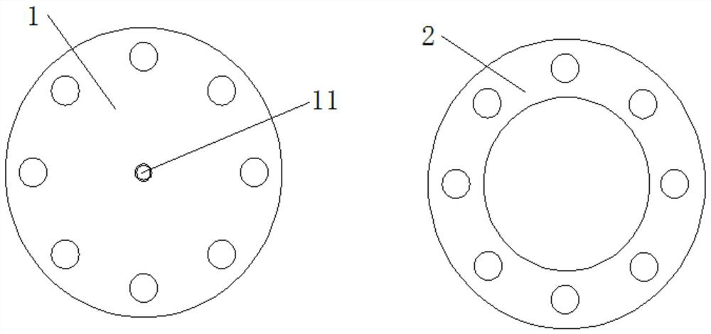
[0034] refer to figure 1 , this embodiment provides an on-site pressing tool for the wafer butterfly valve of a nuclear power plant, which is used for in-situ pressing of the wafer butterfly valve of a nuclear power plant. The flange 1 on the side of the blocking plate and the flange ring 2 on the draining side clamp the wafer butterfly valve of the nuclear power plant in the middle. The bolt hole of the clip butterfly valve is provided with a joint threaded hole 11 for externally connecting the double-headed outer wire joint in the middle, and the flange ring 2 on the exhaust side is a ring structure, and a bolt hole for connecting the clip butterfly valve of the nuclear power plant is provided on it.

[0035] In this embodiment, the size of the flange 1 on the blocking plate side and the flange ring 2 on the venting side are adapted to the caliber of the wafer butterfly valve in a nuclear power plant, and multiple sets can be designed according to the caliber of different va...

Embodiment 2

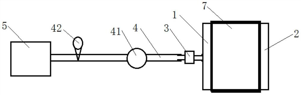
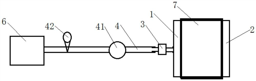
[0046]The difference from Embodiment 1 is that this embodiment provides another on-site pressing system for wafer butterfly valves of nuclear power plants, which is used for on-site pressing of wafer butterfly valves in nuclear power plants. The pressing system includes pressing tools, double-headed outer wire joints 3 , pressing the pipeline 4 and the compressor 6, the pressing tool includes a flange 1 on the side of the blocking plate and a flange ring 2 on the emptying side, and the flange 1 on the side of the blocking plate and the flange ring 2 on the emptying side are connected by bolts The two ends of the wafer butterfly valve 7 of the nuclear power plant to be tested, the flange plate 1 on the side of the blocking plate and the flange ring 2 on the venting side clamp the wafer butterfly valve of the nuclear power plant in the middle, and one end of the double-headed outer wire joint 3 is connected to the flange on the side of the blocking plate. The joint threaded hole ...


PUM


Abstract

The invention relates to a nuclear power station wafer butterfly valve on-site pressing tool and a pressing system, the nuclear power station wafer butterfly valve on-site pressing tool is used for on-site pressing of a nuclear power station wafer butterfly valve, the pressing tool comprises a blocking plate side flange plate and an emptying side flange ring, when the pressing tool is used, the blocking plate side flange plate and the emptying side flange ring clamp the nuclear power station wafer butterfly valve between the blocking plate side flange plate and the emptying side flange ring; the plug board side flange plate is of a disc-shaped structure, a bolt hole used for being connected with the nuclear power station wafer butterfly valve is formed in the outer ring, a connector threaded hole used for being externally connected with a double-end external thread connector is formed in the middle of the plug board side flange plate, and the emptying side flange ring is of a circular ring structure and provided with a bolt hole used for being connected with the nuclear power station wafer butterfly valve. Compared with the prior art, the nuclear power station wafer butterfly valve on-site pressing tool can carry out pressing work conveniently and efficiently on site, and the tool is convenient and easy to carry.

Description

technical field [0001] The invention belongs to a valve maintenance device, in particular to an on-site pressing tool and a pressing system for wafer butterfly valves of nuclear power plants. Background technique [0002] There are a lot of butterfly valves in the condensate polishing system and gas system of nuclear power plants. The connection form is the flange wafer type. The sealing principle of this type of valve is that the clamping bolt tightening force is applied to the valve seat pressure plate to form a seal between the valve seat and the butterfly plate. Force to achieve the sealing effect. In the process of dismantling and overhauling, the existing overhaul method is to transport the valve back from the site and clamp and press it through the valve universal pressing table, which has the following disadvantages: 1. Limited by the size of the pressing table, only small-diameter valves can be pressed ; 2. It is very inconvenient to suppress. If it is a soft seal,...

Claims


Application Information

Patent Timeline
Patent Type & Authority Applications(China)
IPC IPC(8): G01M3/28G01M3/08
CPCG01M3/2869G01M3/086
Inventor 曹洪宇魏杰杨有山田勇郭振坤吕闯
Owner CLP CHINA NUCLEAR POWER ENG TECH
Why Eureka
Try Eureka