
Direct current charging control device of mobile power supply and direct current charging device of mobile power supply

A control device and DC charging technology, applied in battery circuit devices, circuit devices, current collectors, etc., can solve the problems of power supply damage, waste of battery power, unstable output voltage, etc., to save power, control charging time, and protect damage. Effect

Pending Publication Date: 2022-03-15
ZHEJIANG INTEPOWER ELECTRONIC CO LTD
View PDF0 Cites 0 Cited by
  • Summary
  • Abstract
  • Description
  • Claims
  • Application Information

AI Technical Summary

Problems solved by technology

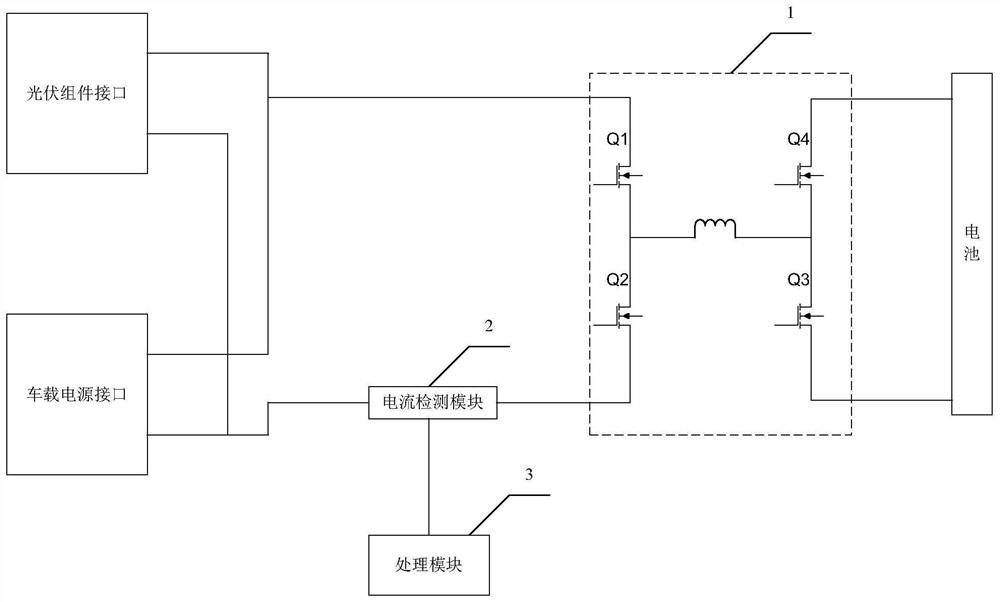
[0002] In the prior art, the power supply charges the battery through a voltage conversion circuit. The power supply can be a photovoltaic module or a vehicle power supply. Since the voltage conversion circuit is a bidirectional circuit, the current can flow from the power supply to the battery, or from the battery to the power supply. During the charging process of the battery, the output voltage of the photovoltaic module will be unstable due to the instability of the light. When the output voltage of the photovoltaic module is converted by the voltage conversion circuit and the output voltage of the voltage conversion circuit is lower than the voltage of the battery, a backflow current will be generated. , that is, the current flows from the battery to the photovoltaic module, which wastes battery power and also causes unnecessary damage to the power supply

Method used


Image

  • Direct current charging control device of mobile power supply and direct current charging device of mobile power supply
  • Direct current charging control device of mobile power supply and direct current charging device of mobile power supply

Examples


Embodiment Construction

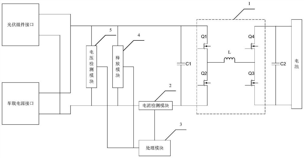
[0040] The core of this application is to provide a DC charging control device for a mobile power supply and a DC charging device for a mobile power supply, which can not only control the charging time, but also prevent the current of the battery from flowing to the power supply, thereby preventing the power supply from being damaged.

[0041] In order to make the purposes, technical solutions and advantages of the embodiments of the present application clearer, the technical solutions in the embodiments of the present application will be clearly and completely described below in conjunction with the drawings in the embodiments of the present application. Obviously, the described embodiments It is a part of the embodiments of this application, not all of them. Based on the embodiments in this application, all other embodiments obtained by persons of ordinary skill in the art without making creative efforts belong to the scope of protection of this application.

[0042] figure...


PUM


Abstract

The invention discloses a direct current charging control device of a mobile power supply and a direct current charging device of the mobile power supply, and the direct current charging control device of the mobile power supply comprises a voltage conversion module, a current detection module and a processing module, and the processing module is used for controlling the voltage conversion module to convert the voltage output by the power supply and then charge the battery, and controlling the voltage conversion module to stop working when the current is smaller than a preset current threshold so as to control the charging time and save electric energy. When backward current is generated, the result output by the current detection module to the processing module is that the current is zero, the current is smaller than a preset current threshold value at the moment, and the processing module still controls the voltage conversion module to stop working. The charging time can be controlled, the current of the battery can be prevented from flowing to the power supply to generate backward current, and the power supply is protected from being damaged.

Description

technical field [0001] The invention relates to the field of mobile energy storage, in particular to a DC charging control device for a mobile power supply and a DC charging device for the mobile power supply. Background technique [0002] In the prior art, the power supply charges the battery through a voltage conversion circuit. The power supply can be a photovoltaic module or a vehicle power supply. Since the voltage conversion circuit is a bidirectional circuit, the current can flow from the power supply to the battery, or from the battery to the power supply. During the charging process of the battery, the output voltage of the photovoltaic module will be unstable due to the instability of the light. When the output voltage of the photovoltaic module is converted by the voltage conversion circuit and the output voltage of the voltage conversion circuit is lower than the voltage of the battery, a backflow current will be generated. , that is, the current flows from the b...

Claims


Application Information

Patent Timeline
Patent Type & Authority Applications(China)
IPC IPC(8): H02J7/00H02J7/35
CPCH02J7/00712H02J7/0029H02J7/35H02J2207/20Y02E10/56
Inventor 卢啸朱璇周懂明罗宇浩
Owner ZHEJIANG INTEPOWER ELECTRONIC CO LTD
Learn More