Converter valve bridge arm submodule with overvoltage suppression function, control method thereof and converter valve

A technology of overvoltage suppression and converter valves, applied in the field of converter valves, can solve problems such as overvoltage, large equipment investment, and endangering the safety of primary equipment, so as to improve tolerance, reduce overvoltage stress, and have large engineering application potential Effect

Pending Publication Date: 2022-03-15
XJ ELECTRIC +1
View PDF5 Cites 0 Cited by
  • Summary
  • Abstract
  • Description
  • Claims
  • Application Information

AI Technical Summary

Problems solved by technology

[0003] There are a large number of DC capacitor devices in the existing MMC-based topology. When the receiving end AC system fails or the converter station ground fault occurs, the system power will be surplus, and the surplus power will charge the module capacitors, resulting in system overvoltage. , seriously endangering the safety of primary equipment
At present, the solution to system power surplus is mainly by installing energy-consuming devices on the AC side or DC side of the system. In the case of AC system faults, putting in energy-consuming devices to consume surplus power can realize fault ride-through of the AC system, but the investment in the entire equipment is relatively high. Large, especially the AC energy consumption device cannot solve the problem of freewheeling overvoltage caused by faults in the receiving station
For the overall freewheeling overvoltage of the sub-module of the single bridge arm of the converter valve caused by the ground fault in the station, the overvoltage limit can also be limited by connecting lightning arresters at both ends of the bridge arm in parallel. However, this method is a passive defense and cannot control the lightning arrester. It also cannot solve the overvoltage problem of the converter valve caused by the failure of the AC system

Method used


Image

  • Converter valve bridge arm submodule with overvoltage suppression function, control method thereof and converter valve
  • Converter valve bridge arm submodule with overvoltage suppression function, control method thereof and converter valve
  • Converter valve bridge arm submodule with overvoltage suppression function, control method thereof and converter valve

Examples


Embodiment Construction

[0036] In order to make the object, technical solution and advantages of the present invention clearer, the present invention will be further described in detail below in combination with specific embodiments and with reference to the accompanying drawings. It should be understood that these descriptions are exemplary only, and are not intended to limit the scope of the present invention. Also, in the following description, descriptions of well-known structures and techniques are omitted to avoid unnecessarily obscuring the concept of the present invention.

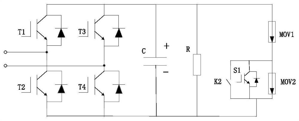
[0037] Please refer to figure 1 , The first aspect of the embodiments of the present invention provides a converter valve bridge arm sub-module with an overvoltage suppression function, including: a power circuit and an overvoltage suppression circuit. The power circuit includes: a first bypass switch, a first power device, a second power device, a DC capacitor and a voltage equalizing resistor. The overvoltage suppress...


PUM


Abstract

The invention discloses a converter valve bridge arm submodule with an overvoltage suppression function. The converter valve bridge arm submodule comprises a power circuit and an overvoltage suppression circuit, the source electrode of the first power device is connected with the drain electrode of the second power device, and the first bypass switch is connected in parallel with the second power device and the connection port of the converter valve single-bridge arm submodule; the anode of the first lightning arrester is connected with the drain electrode of the first power device and one end of the DC capacitor and one end of the voltage-sharing resistor, and the cathode of the first lightning arrester is connected with the anode of the second lightning arrester. The negative electrode of the second lightning arrester is connected with one end of the DC capacitor, one end of the voltage-sharing resistor and the source electrode of the second power device. And the second bypass switch and the third power device are connected in parallel with the second lightning arrester. By adding the overvoltage suppression circuit, the overvoltage stress of the converter valve equipment under the in-station extreme fault working condition and in the alternating current system fault ride-through process is effectively reduced, the alternating current system fault ride-through capacity and the in-station extreme fault endurance capacity of the flexible direct current converter valve equipment are improved, and the large engineering application potential is achieved.

Description

technical field [0001] The invention relates to the technical field of electric equipment, in particular to a converter valve bridge arm sub-module with an overvoltage suppression function, a control method thereof, and a converter valve. Background technique [0002] The flexible DC transmission system based on MMC (Modular Multilevel Converter, modular multilevel converter) has flexible control and can realize independent decoupling control of active power and reactive power. Power supply, power grid black start, multi-terminal DC networking, weak system networking and other fields have great market application prospects. At present, there are several MMC topology application projects in China. [0003] There are a large number of DC capacitor devices in the existing MMC-based topology. When the receiving end AC system fails or the converter station ground fault occurs, the system power will be surplus, and the surplus power will charge the module capacitors, resulting in...

Claims


Application Information

Patent Timeline
Patent Type & Authority Applications(China)
IPC IPC(8): H02M1/32H02J3/36H02M7/5387
CPCH02M1/32H02J3/36H02M7/53871Y02E60/60
Inventor 刘路路韩坤胡四全田颀张磊
Owner XJ ELECTRIC
Why Eureka
Try Eureka