Oil sludge conveying screw pump with anti-blocking function for oil field

A technology for conveying screw and sludge, which is applied to mixers with rotary stirring devices, rotary piston type/swing piston type pump components, rotary piston pumps, etc., which can solve the problem of low service life, easy blockage, and transportation Poor efficiency and other problems, to achieve high-efficiency conveying, avoid material breakage, and improve service life

Pending Publication Date: 2022-03-18
刘云凤
View PDF4 Cites 0 Cited by
  • Summary
  • Abstract
  • Description
  • Claims
  • Application Information

AI Technical Summary

Problems solved by technology

[0005] In order to overcome the shortcomings of the screw pump such as low service life, poor transportation efficiency, and easy clogging, the technical problem of the present inve

Method used


Image

  • Oil sludge conveying screw pump with anti-blocking function for oil field
  • Oil sludge conveying screw pump with anti-blocking function for oil field
  • Oil sludge conveying screw pump with anti-blocking function for oil field

Examples


Embodiment 1

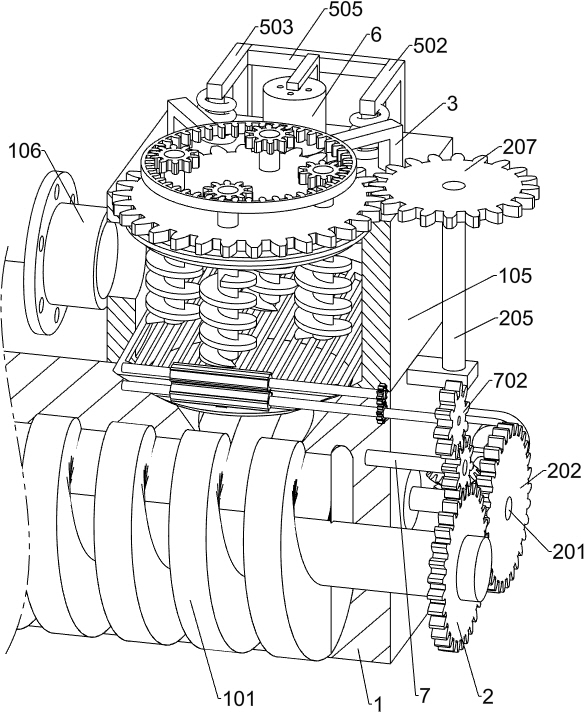
[0033] A screw pump for transporting sewage sludge in oil fields with anti-clogging function, such as Figure 1-3 As shown, it includes a housing 1, a first screw 101, a second screw 102, a base 103, a drive motor 104, an intermediate compartment 105, a material inlet 106, a material outlet 107, an agitating mechanism, a power mechanism, an induction mechanism, and a discharge mechanism. Air mechanism and crushing mechanism, the first screw 101 and the second screw 102 are rotated in the housing 1, the first screw 101 and the second screw 102 are engaged, the right end of the housing 1 is fixed with a base 103, and the upper end of the base 103 is fixed There is a driving motor 104, the output shaft end of the driving motor 104 is fixedly connected to the right end of the first screw 101, the upper surface of the right part of the housing 1 is fixedly connected to the middle compartment 105, the left end of the middle compartment 105 is fixedly connected to the feed port 106, a...

Embodiment 2

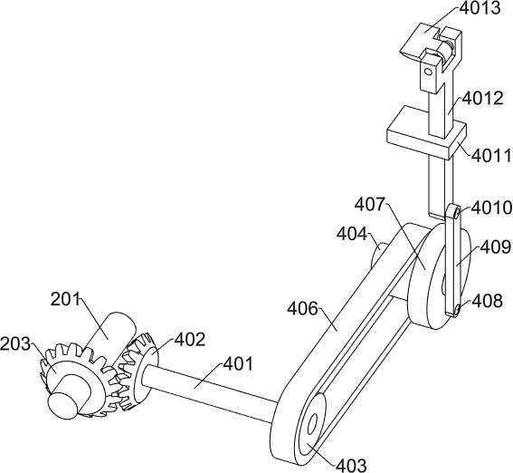
[0037] On the basis of Example 1, such as Figure 4 and Figure 5 As shown, the stirring mechanism includes a first spur gear 2, a first transmission shaft 201, a second spur gear 202, a first helical gear 203, a first fixed frame 204, a second transmission shaft 205, a second helical gear 206, a first Three spur gears 207, gear turntable 208, rotating shaft 209 and push assembly, the first spur gear 2 is affixed to the right end of the first screw rod 101, the first transmission shaft 201 is affixed to the right end of the second screw rod 102, the right end of the first transmission shaft 201 A second spur gear 202 is fixedly connected, and the second spur gear 202 meshes with the first spur gear 2. The right part of the first transmission shaft 201 is fixedly connected with a first helical gear 203, and the first helical gear 203 is located on the left side of the second spur gear 202. The right end of the housing 1 is fixedly connected with a first fixed frame 204, and th...

Embodiment 3

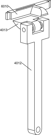
[0044] On the basis of Example 2, such as Image 6 and Figure 7 As shown, the power mechanism includes a second fixed frame 4, a third transmission shaft 401, a third helical gear 402, a first pulley 403, a first rotating shaft 404, a second pulley 405, a belt 406, a runner 407, a second Two rotating shafts 408, movable rod 409, the third rotating shaft 4010, the third fixed mount 4011, the first sliding rod 4012 and the rotating block 4013, the upper surface of the rear part of the base 103 is fixedly connected with the second fixed mount 4, the second fixed mount 4 top A third transmission shaft 401 is provided for rotation, and the front end of the third transmission shaft 401 is fixedly connected with a third helical gear 402, the third helical gear 402 meshes with the first helical gear 203, and the rear end of the third transmission shaft 401 is fixedly connected with a first belt Wheel 403, the rear surface of the housing 1 is rotated with a first shaft 404, the rear ...


PUM


Abstract

The invention relates to the field of oil field oil sludge conveying, in particular to an oil field oil sludge conveying screw pump with an anti-blocking function. The technical problems that a screw pump is short in service life, poor in transportation efficiency and prone to blockage are solved. According to the technical scheme, the oil sludge conveying screw pump with the anti-blocking function for the oil field comprises a shell, a middle cabin, a stirring mechanism, a power mechanism, a sensing mechanism, an exhaust mechanism and a crumbling mechanism, the middle cabin is fixedly connected to the upper surface of the right portion of the shell, the stirring mechanism is arranged in the middle cabin, the power mechanism is arranged on the right portion of the shell, and the sensing mechanism is arranged on the upper surface of the shell. A sensing mechanism and an exhaust mechanism are arranged on the rear portion of the middle cabin, and a crumbling mechanism is fixedly connected to the lower portion of the middle cabin. The stirring mechanism stirs and pushes oil sludge, equipment blockage is avoided, meanwhile, the transportation efficiency of the equipment is improved, the service life of the equipment is prolonged through the crumbling mechanism, the sensing mechanism, the exhaust mechanism and the power mechanism work in a matched mode, the phenomenon of material breakage of the equipment is avoided, and long-time normal work of the equipment is achieved.

Description

technical field [0001] The invention relates to the field of oilfield sludge transportation, in particular to a screw pump for oilfield sewage sludge transportation with anti-clogging function. Background technique [0002] Sludge refers to the production process of oil fields, due to crude oil extraction, storage, gathering and transportation, processing, and crude oil production fluid treatment process, which is famous for containing crude oil or certain components in crude oil. It is mainly divided into: ground sludge, clear tank sludge, flotation scum, etc. Sludge is harmful to human body, plants and aquatic organisms. The oil and gas evaporated in the air can irritate the skin, eyes and respiratory organs, and make the land lose plant growth. It is difficult to handle and repair, and it is one of the main pollutants in the petroleum and petrochemical industries. [0003] During the process of pumping the sludge by the screw pump, due to the poor fluidity of the sludge,...

Claims


Application Information

Patent Timeline
IPC IPC(8): F04C2/16F04C13/00F04C15/00B01F27/922
CPCF04C2/16F04C13/001F04C13/005F04C13/007F04C15/00
Inventor 刘云凤
Owner 刘云凤
Why Eureka
Try Eureka