Backlight module and display device

A backlight module and display device technology, applied in the direction of identification devices, instruments, etc., can solve problems such as unfavorable, high cost of reflective sheets, and reduce costs, and achieve the effects of uniform light transition, saving production costs, and low cost

Active Publication Date: 2022-03-18
MIANYANG HKC OPTOELECTRONICS TECH CO LTD +1
View PDF8 Cites 9 Cited by
  • Summary
  • Abstract
  • Description
  • Claims
  • Application Information

AI Technical Summary

Problems solved by technology

[0003] However, relying on the reflector to reflect at the gap will make the display panel as a whole, the transition between the light emitted by the lamp panel and the light reflected by the reflector is relatively strong, and the fill light effect for the gap is not very good, and the reflection The cost of chips is high, which is not conducive to reducing costs

Method used


Image

  • Backlight module and display device
  • Backlight module and display device
  • Backlight module and display device

Examples


Embodiment 1

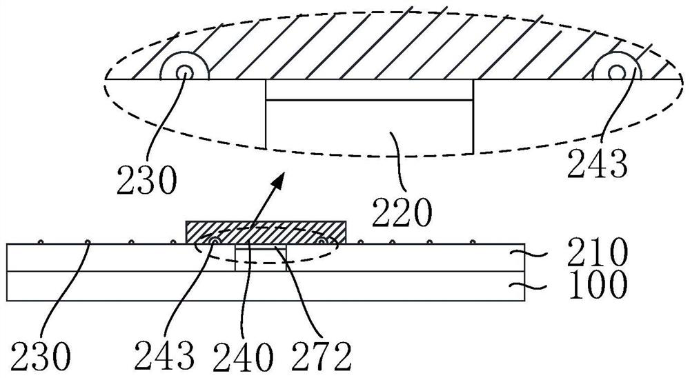
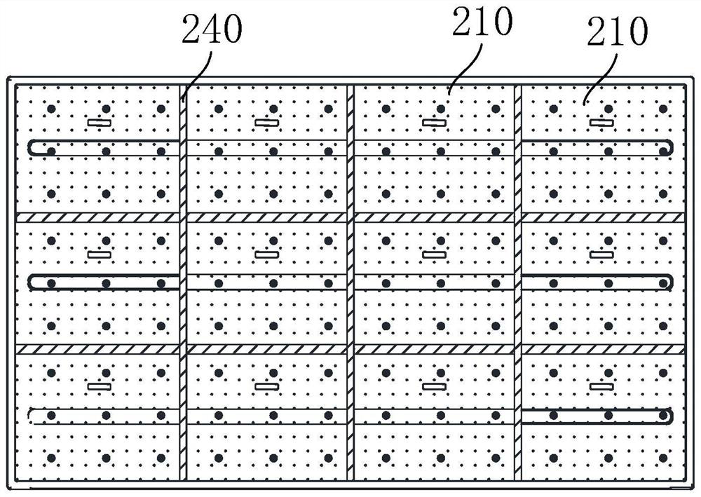
[0029] figure 1 It is a cross-sectional schematic diagram of a diffuser plate installed in the gap of a spliced ​​lamp panel according to the first embodiment of the present application, as shown in figure 1 As shown, a backlight module 20 is disclosed. The backlight module includes a spliced ​​lamp panel 200. The spliced ​​lamp panel 200 is formed by splicing a plurality of lamp panels 210. There are gaps between adjacent lamp panels 210. 220, the backlight module 20 further includes a diffuser plate 240, the diffuser plate 240 is arranged at a position corresponding to the gap 220, and the diffuser plate 240 covers at least one row of light-emitting elements on at least one of the lamp panels 210 Diodes 230, at least part of the light emitting diodes 230 on the lamp board 210 are not covered.

[0030] Specifically, the diffuser plate 240 can only cover the light emitting diodes 230 on one lamp panel 210, and the diffuser plate 240 can also cover the light emitting diodes 23...

Embodiment 2

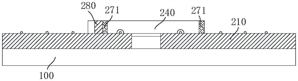
[0049] Figure 5 It is a cross-sectional schematic diagram of a diffuser plate installed in the gap of a spliced ​​lamp panel according to the second embodiment of the present application, as shown in Figure 5 As shown, as the second embodiment of the present application, the difference from the first embodiment is that a diffuser plate 240 is disclosed, and the diffuser plate 240 includes a horizontal portion 244 and a vertical portion 245, and the horizontal portion 244 Set horizontally with the lamp panel 210, the vertical portion 245 is vertically set with the horizontal portion 244, and the vertical portion 245 is set at the gap 220, one end is connected with the horizontal portion 244, and the other end It is fixedly connected with the backplane 100 . And there is a safety distance between the vertical part 245 and the lamp panel 210, and the diffusion plate 240 is fixed on the back panel 100 through the vertical part 245, which can prevent the thermal expansion of the...

Embodiment 3

[0051] Figure 6 It is a cross-sectional schematic diagram of a diffuser plate installed in the gap of a spliced ​​lamp panel according to the third embodiment of the present application, as shown in Figure 6 As shown, as the second embodiment of the present application, the difference from the first embodiment is that a lamp panel 210 is disclosed, and the lamp panel 210 includes a support part 212 of a main body part 211, and the support part 212 is set On the side of the main body part 211 close to the slit 220 , the diffuser plate 240 covers the slit 220 , the side of the diffuser plate 240 away from the slit 220 is the first surface, and the side of the diffuser plate 240 close to the slit 220 One side is the second surface, the first surface abuts against the support portion 212, the second surface is flush with the light-emitting surface of the lamp board 210, and the light-emitting diodes 230 covered by the diffusion plate 240 are located on the Between the supportin...


PUM

PropertyMeasurementUnit
thicknessaaaaaaaaaa

Abstract

The invention discloses a backlight module and a display device, the backlight module comprises a splicing lamp panel, the splicing lamp panel is formed by splicing a plurality of lamp panels, a gap is formed between every two adjacent lamp panels, the backlight module further comprises a diffusion plate, the diffusion plate is arranged at the position corresponding to the gap, and the diffusion plate is arranged in the position corresponding to the gap. The diffusion plate covers at least one row of light-emitting diodes on at least one lamp panel, and at least part of the light-emitting diodes on the lamp panel are not covered. The diffusion plate is arranged at the gap and covers the at least one row of light emitting diodes, close to the gap, in the at least one lamp panel, light on the lamp panel is uniformized into the diffusion plate, light transition between the gap and the lamp panel is smoother on the basis that light supplementing is conducted on the gap, and the light emitting efficiency is improved. And the manufacturing cost of the diffusion plate is lower, so that the production cost is saved.

Description

technical field [0001] The present application relates to the field of display technology, in particular to a backlight module and a display device. Background technique [0002] At present, there is a certain gap between the two adjacent light panels of the Mini LED splicing screen to provide space for the thermal expansion and contraction of the light panels, resulting in problems such as dark lines appearing in the corresponding gaps when the display device is displayed. The common practice is to use The reflective sheet is used to cover the gap between adjacent light panels, and to fill the gap. [0003] However, relying on the reflector to reflect at the gap will make the display panel as a whole, the transition between the light emitted by the lamp panel and the light reflected by the reflector is relatively strong, and the fill light effect for the gap is not very good, and the reflection The cost of the chip is relatively high, which is not conducive to reducing the...

Claims


Application Information

Patent Timeline
Patent Type & Authority Applications(China)
IPC IPC(8): G09F9/33
CPCG09F9/33G02B6/0025G02B6/0055G02B6/0068G02B6/0073
Inventor 曾智杨晓辉袁海江
Owner MIANYANG HKC OPTOELECTRONICS TECH CO LTD
Why Eureka
Try Eureka