
Double-floating type mounting structure of connector socket

A connector socket and installation structure technology, which is applied to the parts, connections, coupling devices, etc. of the connection device, can solve the problems that cannot meet the requirements of the special use environment, the installation screws cannot be installed smoothly, and the installation screws cannot be installed, etc. , to prevent water and dust from entering the connector and inside the cabinet, protect the cabinet equipment, and achieve low cost

Pending Publication Date: 2022-03-18
TAIZHOU HANGYU ELECTRICAL DEVICE
View PDF0 Cites 0 Cited by
  • Summary
  • Abstract
  • Description
  • Claims
  • Application Information

AI Technical Summary

Problems solved by technology

At present, the electrical connectors in the industry adopt the structure of fixed contacts and fixed mounting nuts, which cannot meet the requirements of this special use environment, and there are the following problems:
Since the socket is welded on the printed board, an upward force is applied to the printed board, causing the printed board to break and damage
[0005] 2. Between the cabinet and the panel, between the printed board and the cabinet, and between the multi-layer printed boards, screws and studs are often used for assembly. Each connection will have a positional tolerance. When the positional tolerance is accumulated, the socket's The second installation hole is misaligned with the opening of the cabinet panel, so that the installation screws cannot be installed. At the same time, when the installation personnel of the cabinet screw the installation screws into the second installation hole of the socket, it is easy to have a certain angle deflection and the installation screws cannot be installed smoothly. Insert, you need to re-position the mounting screws vertically before screwing in, which will affect the assembly efficiency

Method used


Image

  • Double-floating type mounting structure of connector socket
  • Double-floating type mounting structure of connector socket
  • Double-floating type mounting structure of connector socket

Examples


Embodiment

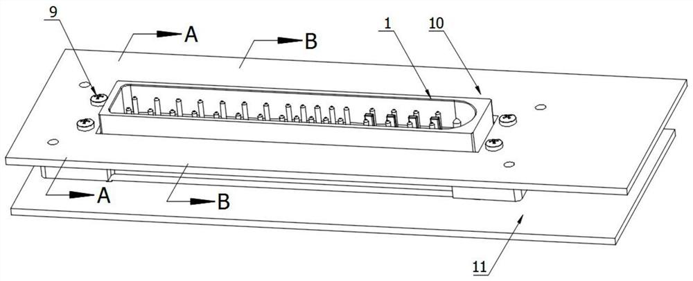
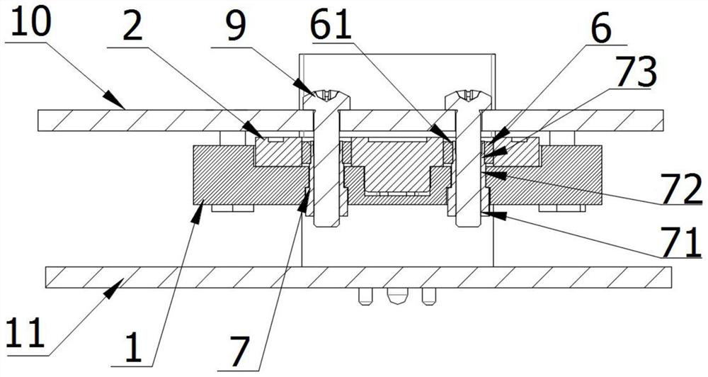
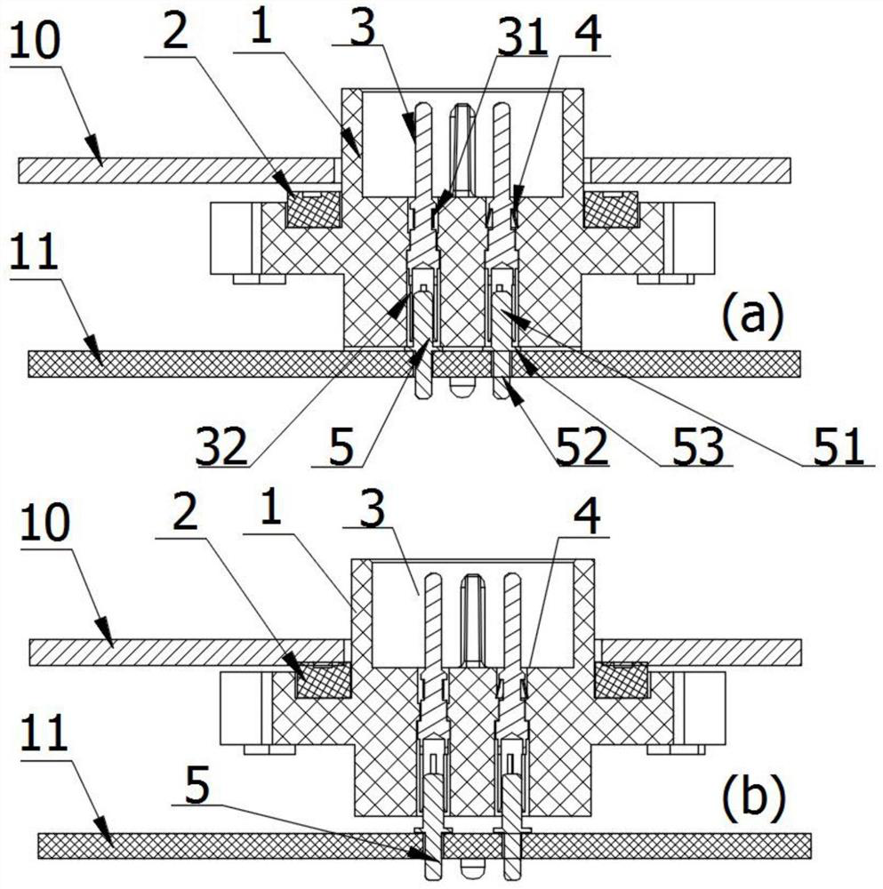
[0036] Such as figure 1 , figure 2 , Figure 4 , Image 6 As shown, this embodiment is a double-floating installation structure of a connector socket, including a socket, a cabinet panel 10, a gasket 6 and a floating riveting tube 7, the socket includes a base 1, and a fixed riveting tube 8 is arranged on the base 1 , the base 1 is sequentially set with a gasket 2 and a cabinet panel 10 from bottom to top, and the same mounting screw 9 is movably inserted in the through hole opened on the gasket 2 and the cabinet panel 10, the base 1, the gasket 2, The mounting screws 9 and the cabinet panel 10 constitute a floating contact structure;

[0037] In the floating structure of the contact piece: the base 1 is socketed with the gasket 2 and the cabinet panel 10, and the mounting screw 9 penetrates through the through holes on the cabinet panel 10 and the gasket 2 to thread the floating riveting tube 7; the mounting screw 9 makes the socket and When the cabinet panel 10 is tight...


PUM


Abstract

The invention relates to the technical field of connector socket installation, in particular to a double-floating type installation structure of a connector socket, the socket comprises a base, the base is sequentially sleeved with a sealing gasket and a cabinet panel from bottom to top, and the same installation screw is movably inserted in through holes formed in the sealing gasket and the cabinet panel. And the base, the sealing gasket, the mounting screw and the cabinet panel form a contact floating type structure. The double-floating installation type structure is composed of a contact piece floating type structure and a locking floating type structure, has the advantages of being reliable in structure, wide in application range, convenient to install and the like, solves the problems that when a welding plate type connector is locked, fixed and sealed, a printed board is damaged due to stress, the compression amount of a sealing gasket is not enough, and the sealing performance is not qualified, and improves the sealing performance. The cabinet equipment is effectively protected; the invention relates to a double-floating type mounting structure of a connector socket. The double-floating type mounting structure is suitable for mounting an intelligent distributed DTU automatic detection terminal cabinet with a complex structure.

Description

technical field [0001] The invention relates to the technical field of connector socket installation, in particular to a double-floating installation structure of a connector socket. Background technique [0002] The connector is an indispensable part of electronic equipment. The function of the connector is to build a communication bridge between the blocked or isolated circuits in the circuit, so that the current can flow and the circuit can realize the predetermined function. [0003] The internal structure of the intelligent distributed DTU automatic detection terminal cabinet is complex and there are many components, which put forward various requirements for the supporting connectors, especially the welding feet of the connector socket are directly welded on the printed board inside the cabinet, and the socket The sealing gasket on the upper surface and the cabinet cover plate are compressed to form a sealed and waterproof structure. At present, the electrical connect...

Claims


Application Information

Patent Timeline
IPC IPC(8): H01R13/631H01R13/52H01R13/46
CPCH01R13/6315H01R13/5202H01R13/46
Inventor 宋亮卞如民叶留芳王永振
Owner TAIZHOU HANGYU ELECTRICAL DEVICE
Learn More