Material bar pressing and holding mechanism

A technology of pressing and holding mechanism and material bar, which is applied to metal processing mechanical parts, manufacturing tools, positioning devices, etc., can solve the problem of cumbersome clamping process, achieve convenient and fast clamping, simplify the feeding process, and reduce the feeding process. Effect

Active Publication Date: 2022-03-22
GUANGDONG UCAN ROBOT TECH CO LTD
View PDF11 Cites 0 Cited by
  • Summary
  • Abstract
  • Description
  • Claims
  • Application Information

AI Technical Summary

Problems solved by technology

[0005] The technical problem to be solved by the present invention is to provide a

Method used


Image

  • Material bar pressing and holding mechanism
  • Material bar pressing and holding mechanism
  • Material bar pressing and holding mechanism

Examples


Embodiment Construction

[0029] In order to facilitate the understanding of those skilled in the art, the present invention will be further described below in conjunction with the embodiments and accompanying drawings, and the contents mentioned in the embodiments are not intended to limit the present invention.

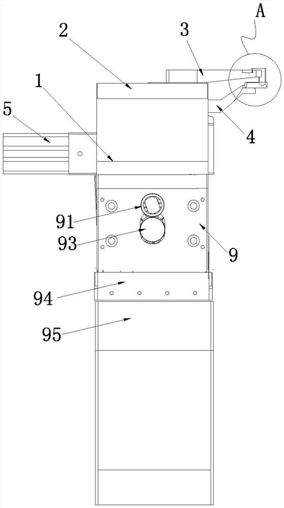
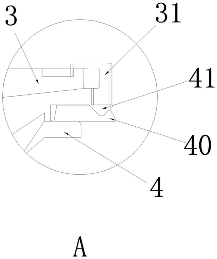
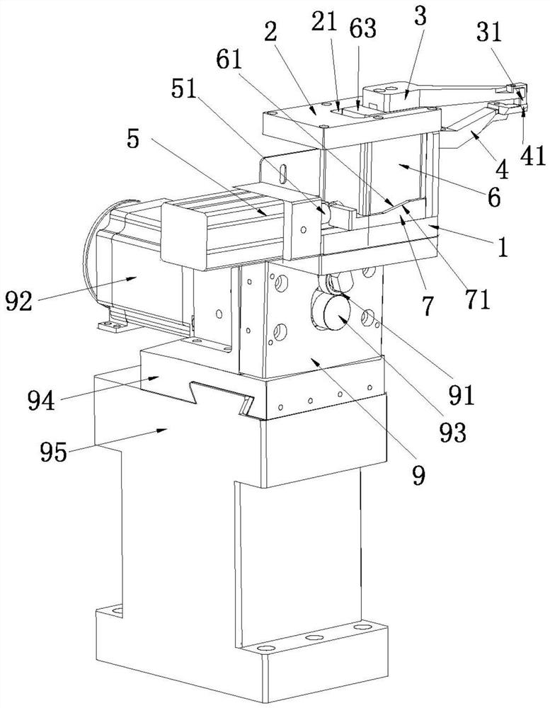
[0030] A specific implementation of a rod holding mechanism of the present application, such as figure 1 As shown, it includes an upper pressing arm 3 , a lower pressing arm 4 , a hollow base 1 and a top plate 2 fixedly installed above the base 1 . It should be noted that the base 1 can be spliced ​​by a plurality of connecting plates. Specifically, a fixed bottom plate can be arranged, and then four vertically arranged connecting plates can be fixed on the periphery of the bottom plate to form a hollow Base 1.

[0031] Preferably, the ratio of the heights of the upper pressing arm 3 and the lower pressing arm 4 is 0.1-10.

[0032] In this embodiment, one end of the lower pressing arm 4 is...


PUM


Abstract

The invention relates to the technical field of milling cutter machining, in particular to a charge bar pressing and holding mechanism which comprises an upper pressing and holding arm, a lower pressing and holding arm, a hollow base and a top plate fixedly mounted above the base. One end of the lower hold-down arm is fixedly mounted on the side of the base, and a clamping groove is formed in the other end of the lower hold-down arm; one end of the upper hold-down arm is provided with a hold-down piece, and the other end of the lower hold-down arm is provided with a guide block located in the base; a movable channel is formed in the top plate; a mounting part which penetrates through the movable channel and can slide along the movable channel is arranged on the top end face of the guide block, the mounting part is fixedly connected with the lower hold-down arm, and an elastic piece for driving the guide block to move downwards is arranged between the top plate and the guide block; the base is further provided with a driving mechanism for driving the guide block to move upwards and driving the guide block to slide in the horizontal direction. Compared with the prior art, the material bar is pressed in an up-and-down clamping mode, so that the feeding procedure is reduced, clamping is more convenient and faster, the clamping time is shortened, and the working efficiency is improved.

Description

technical field [0001] The invention relates to the technical field of milling cutter processing, in particular to a material rod pressing mechanism. Background technique [0002] The structure of the existing milling cutter includes a straight rod and a cutter head formed on the end of the straight rod. The structure of the cutter head is complicated and various cutting edges need to be processed according to the requirements. However, all current milling cutters are prepared by processing rods. Formed, the material rod is specifically a cylindrical straight rod. [0003] In practical applications, it is necessary to process a blade at the end of the material rod, therefore, a clamping mechanism for clamping the material rod and a grinding mechanism for forming the blade are required. Existing clamping mechanisms generally adopt left and right clamping to clamp the material rod. [0004] Refer to the patent document with the patent number CN202011376902.7, which discloses...

Claims


Application Information

Patent Timeline
IPC IPC(8): B23Q3/08
CPCB23Q3/08B23Q2703/04
Inventor 王俊锋黄春雷王哲
Owner GUANGDONG UCAN ROBOT TECH CO LTD
Why Eureka
Try Eureka