

Multi-rotor unmanned aerial vehicle capable of being quickly folded
A multi-rotor unmanned aerial vehicle, fast technology, applied in the direction of rotorcraft, unmanned aircraft, fuselage, etc., can solve the problem that the arm is not easy to be transported and stored as a whole, so that the structural performance is not affected and normal use is guaranteed , the effect of reducing the occupied space
- Summary
- Abstract
- Description
- Claims
- Application Information
AI Technical Summary
Problems solved by technology
Method used
Image

Examples
Embodiment 1
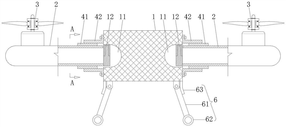
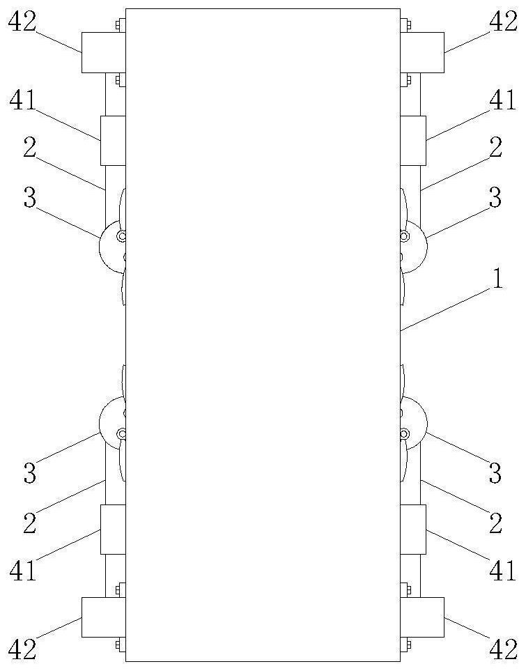
[0029] A rapidly foldable multi-rotor UAV, such as Figure 1-3 As shown, it includes a fuselage 1 , a plurality of arms 2 installed on the fuselage 1 , and a power assembly 3 installed on each arm 2 . Among them, the fuselage 1 is configured as a rectangular shell-shaped structure as a whole, and is equipped with components such as a power supply for supporting flight, flight control equipment, and communication equipment. Among them, the machine arm 2 is preferably configured as a cylindrical structure, and there are four machine arms 2. The four machine arms 2 are symmetrically installed on two opposite sides of the fuselage 1 in pairs, and are located on the fuselage 1. The two arms 2 on the same side are respectively located at the two ends of the fuselage 1, that is, the multi-rotor UAV is in an H-shaped configuration when in use. In other preferred embodiments, the installation position of the machine arm 2 can also be suitable for the multi-rotor drone to be in an X or...
Embodiment 2
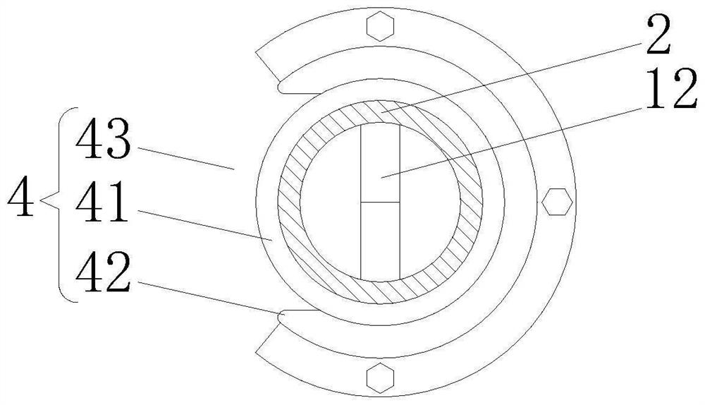
[0035] The difference between it and Embodiment 1 is that this embodiment proposes another structural form of the fixing mechanism 4, in this embodiment, such as Figure 4As shown, the fixing mechanism 4 is configured as a limit bracket 44 fixedly installed on the fuselage 1, and the limit bracket 44 is provided with a limit groove adapted to the outer wall of the machine arm 2, and the limit groove is made of an elastic material. , and the opening of the limiting slot is smaller than the diameter of the arm 2 . In this embodiment, the specific configuration of the limit bracket 44 is cylindrical as a whole, and an axially extending through groove is provided on the circumferential side wall of the limit bracket 44, so that the cylindrical limit bracket with the through groove 44 forms the above-mentioned limiting groove. It is so arranged that when the machine arm 2 rotates to the limit groove on the limit bracket 44, the limit groove is forced to deform and expand, so that ...
Embodiment 3
[0037] The difference from Embodiment 1 is that in this embodiment, the above-mentioned fixing mechanism 4 includes two lock sleeves 42, and the two lock sleeves 42 are fixedly connected to each other, and the axial gaps 43 on the two lock sleeves 42 communicate with each other. , so that the machine arm 2 can rotate from one lock sleeve 42 to the other lock sleeve 42 during the rotation process, as Figure 5 shown. The two lock sleeves 42 are respectively used to fix the arm 2 at the above-mentioned flying position and folded position. Moreover, it only needs to arrange two locking sleeves 42 to be perpendicular to each other. And it can be understood that the hinge point (i.e. hinge 12) between the machine arm 2 and the fuselage 1 is located at the position where the axes of the two lock sleeves 42 intersect, so as to ensure that the machine arm 2 can be in the folded position and the flying position respectively with the two The two lock sleeves 42 are coaxial to realize ...
PUM
 Abstract
Description
Claims
Application Information