
Material transmittance measuring method and material transmittance measuring device

A measurement method and a technology of a measurement device, which are applied in the field of optical measurement, can solve the problems that the diffusion conditions of the integrating sphere cannot be consistent, and the light measurement device cannot accurately reflect the transmittance of materials, etc.

Pending Publication Date: 2022-03-22
杭州通尚光电有限公司
View PDF0 Cites 0 Cited by
  • Summary
  • Abstract
  • Description
  • Claims
  • Application Information

AI Technical Summary

Problems solved by technology

[0003] In actual use, the state of the integrating sphere changes when the sample is placed or not. When there is a sample, the surface of the sample also constitutes a part of the inner wall of the integrating sphere, and the diffusion conditions in the integrating sphere are changed, resulting in the optical measurement device The change of the received optical signal cannot accurately reflect the transmittance of the material
[0004] In order to make up for this deficiency, the existing technology eliminates the difference between placing the sample and not placing the sample by opening a new compensation interface near the sample installation port of the integrating sphere. This method can largely eliminate the error, but it still cannot completely Make the diffusion conditions in the integrating sphere of the two states exactly the same

Method used


Image

  • Material transmittance measuring method and material transmittance measuring device

Examples


Embodiment Construction

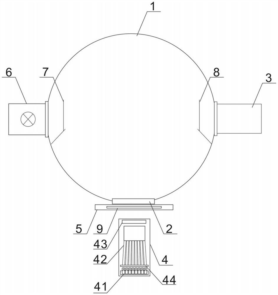
[0024] The implementation of the present application will be described in detail below with reference to the accompanying drawings and examples, so as to fully understand and implement the implementation process of how the present application uses technical means to solve technical problems and achieve technical effects.

[0025] The material transmittance measurement method provided in this embodiment is based on an integrating sphere, and specifically belongs to the (0 / d) vertical / diffuse measurement method. In this embodiment, an auxiliary light source is set on the integrating sphere, and by placing the sample and not placing the sample, the difference in the diffuse reflection conditions in the integrating sphere when the tested sample is placed and when the tested sample is not placed is respectively measured, specifically,

[0026] 1) Without placing the sample to be tested on the opening, test the measured value T1 of the main light source;

[0027] 2) No sample to be ...


PUM


Abstract

The invention belongs to the technical field of optical detection, and particularly relates to a material transmittance measuring method which comprises the following steps: arranging an auxiliary light source on an integrating sphere, respectively measuring the difference of diffuse reflection conditions in the integrating sphere when a sample to be measured is placed and when the sample to be measured is not placed, calculating and eliminating the difference, and finally obtaining the accurate material transmittance. In addition, a material transmittance measuring device is included, the measuring device comprises a measuring integrating sphere and a main light source assembly right facing the measuring integrating sphere, and a light inlet is formed in the measuring integrating sphere and located in an emergent light path of the main light source assembly; the measuring device further comprises a light measuring device installed on the measuring integrating sphere, the measuring device further comprises an auxiliary light source, and emergent light of the auxiliary light source directly enters the measuring integrating sphere. Through the device, the state change of the integrating sphere can be accurately measured when a sample is placed or not placed, and the change is eliminated during calculation, so that the transmittance of a material is accurately measured.

Description

technical field [0001] The invention belongs to the technical field of optical measurement, and specifically includes a material transmittance measurement method and a material transmittance measurement device. Background technique [0002] At present, the integrating sphere method is often used to measure the transmittance of materials. In CIE15, there are two methods involving the integrating sphere measurement method, one is (d / 0) diffuse / perpendicular measurement method, and the other is (0 / d) Vertical / diffuse measurement method. When the d / 0 method is used, a light source and a light outlet are set on the integrating sphere, the light emitted by the light source is reflected by the integrating sphere and then exits through the light outlet, and the sample to be measured is set at the light outlet of the integrating sphere, and the light outlet of the integrating sphere Set the light measuring instrument at the opposite position, measure the light signal when the sampl...

Claims


Application Information

Patent Timeline
IPC IPC(8): G01N21/59G01N21/01
CPCG01N21/59G01N21/01
Inventor 李燕虞建栋
Owner 杭州通尚光电有限公司
Learn More