A kind of anti-shake camera drive device

A driving device and anti-shake technology, which is applied in the direction of developing and printing devices, focusing devices, projection devices, etc., can solve the problems of complicated assembly, easy-to-break solder joints occupying space, and unclear photos, so as to enhance the compensation effect and solve solder joint occupation If the space is too high, the effect of improving the anti-shake performance

Active Publication Date: 2022-08-09
辽宁中蓝光电科技有限公司
View PDF0 Cites 0 Cited by
  • Summary
  • Abstract
  • Description
  • Claims
  • Application Information

AI Technical Summary

Problems solved by technology

[0004] The purpose of the present invention is to provide an anti-shake camera drive device with a more reasonable structure and more reliable use, to solve the problems of complicated assembly and easy breakage of the existing compensation system using suspension wires and excessive space occupied by solder joints, focusing and The anti-shake translation compensation shares the same suspension component, which significantly improves the anti-shake performance, enhances the effect of motor focus and anti-vibration translation compensation, solves the problem of unclear photos caused by shaking during shooting, and prolongs the service life

Method used


Image

  • A kind of anti-shake camera drive device
  • A kind of anti-shake camera drive device
  • A kind of anti-shake camera drive device

Examples


Embodiment 1

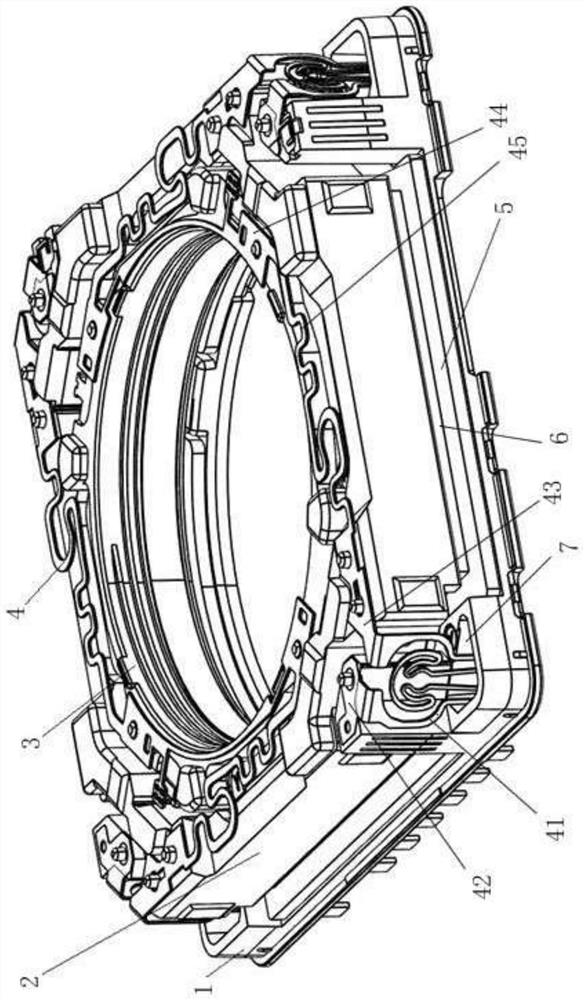
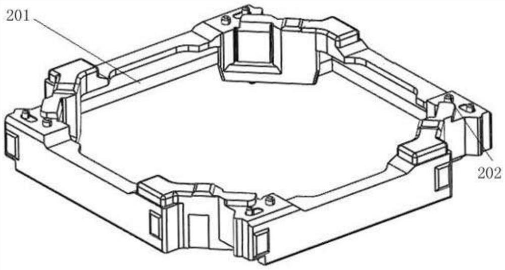
[0037] like Figure 1-Figure 15 As shown, the anti-shake camera driving device includes a base 1, a protective shell 13, an OIS assembly disposed in the protective cavity formed by the base 1 and the protective shell 13, an AF assembly disposed inside the OIS carrier 2 of the OIS assembly, The elastic sheet assembly between the OIS carrier 2 of the OIS assembly and the AF carrier 3 of the AF assembly and the base 1 is a closed-loop control assembly for detecting the movement of the OIS carrier 2 and the AF carrier 3 relative to the base 1 . The elastic piece assembly includes an upper elastic piece 4 and a lower elastic piece 9 .

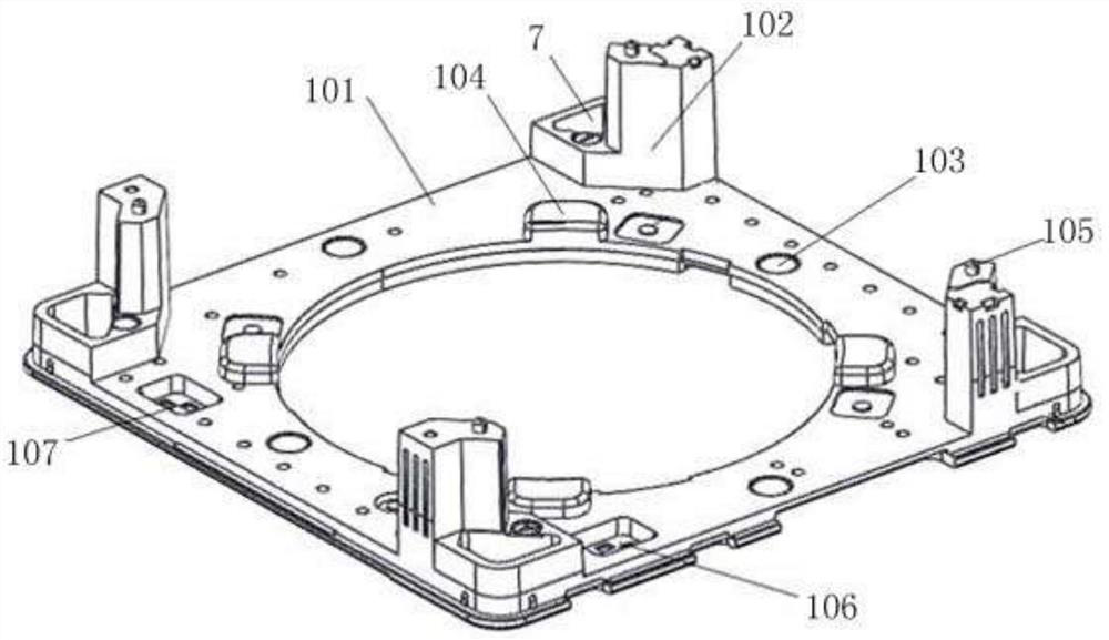
[0038] Wherein, the four corners of the upper surface of the bottom plate 101 of the base 1 are respectively provided with damping grooves 7 for storing damping glue. The number of damping grooves 7 is the same. The upper elastic sheet 4 has a fixed part I 44 connected with the top surface of the AF carrier 3, a fixed part II 43 connected with the t...

Embodiment 2

[0048] The anti-shake camera drive device, such as Figure 16 As shown, the OIS coil 5 of the OIS assembly adopts a split racetrack coil, and the number of the split racetrack coils is four, which corresponds to the four magnets 601 of the magnet assembly 6 one-to-one. A plurality of positioning bosses 109 corresponding to the split racetrack coils are provided on four sides of the upper surface of the base plate 101 , and the split racetrack coils are fixed to the base plate 101 through the positioning bosses 109 .

[0049] Others are the same as in Example 1.


PUM


Abstract

The invention relates to a novel anti-shake camera drive device, comprising a base, a protective shell, an OIS assembly, an AF assembly, a shrapnel assembly and a closed-loop control assembly. The shrapnel assembly includes an upper shrapnel and a lower shrapnel. The four corners of the upper surface are respectively provided with damping grooves, the base is provided with a retaining wall at one side of the damping groove, and the upper elastic piece has a fixed part I connected with the top surface of the AF carrier, and a fixed part II connected with the top surface of the OIS carrier. The fixed part III connected to the top surface of the retaining wall, the chord part I connected between the fixed part I and the fixed part II, the bending connection part connected between the fixed part II and the fixed part III, the bending connection part Insert the lower end into the damping glue of the damping groove. The device solves the problems that the existing compensation system using suspension wires is complicated and easy to break and occupies too much space for solder joints. The focusing and anti-shake translation compensation share the same suspension component, which significantly improves the anti-shake performance, and enhances the motor focusing and stability. Anti-vibration translation compensation effect.

Description

technical field [0001] The invention relates to an optical product driving device, in particular to an anti-shake camera driving device, which is suitable for driving an optical element to translate along more than two axes and is shock-proof. Background technique [0002] At present, the optical systems of common handheld optical products on the market, such as digital cameras, video cameras, and mobile phones, are composed of an optical lens group and a camera driving device. During the shooting process, it is easy to be shaken by external forces, such as hand-held, vehicle movement, and external environmental factors that cause the device to shake, resulting in problems such as inability to image clearly or blurred images. The common image compensation system for mobile phones on the market uses the lens translation method to compensate for the optical path offset problem. In this compensation mechanism, the movable part is suspended and translated by the suspension wire ...

Claims


Application Information

Patent Timeline
Patent Type & Authority Patents(China)
IPC IPC(8): G03B5/00G02B7/09G03B13/36G03B30/00H04N5/232
CPCG03B5/00G02B7/09G03B13/36G03B30/00H04N23/687
Inventor 吴发权王万军宋秉儒
Owner 辽宁中蓝光电科技有限公司
Why Eureka
Try Eureka