
Foot pad linkage mechanism and notebook computer

A linkage mechanism and foot pad technology, applied in the direction of electrical digital data processing, instruments, digital data processing components, etc., can solve problems such as inconvenient use, and achieve the effects of convenient use, improved air intake efficiency, and flexible installation

Pending Publication Date: 2022-03-22
紫光计算机科技有限公司
View PDF0 Cites 3 Cited by
  • Summary
  • Abstract
  • Description
  • Claims
  • Application Information

AI Technical Summary

Problems solved by technology

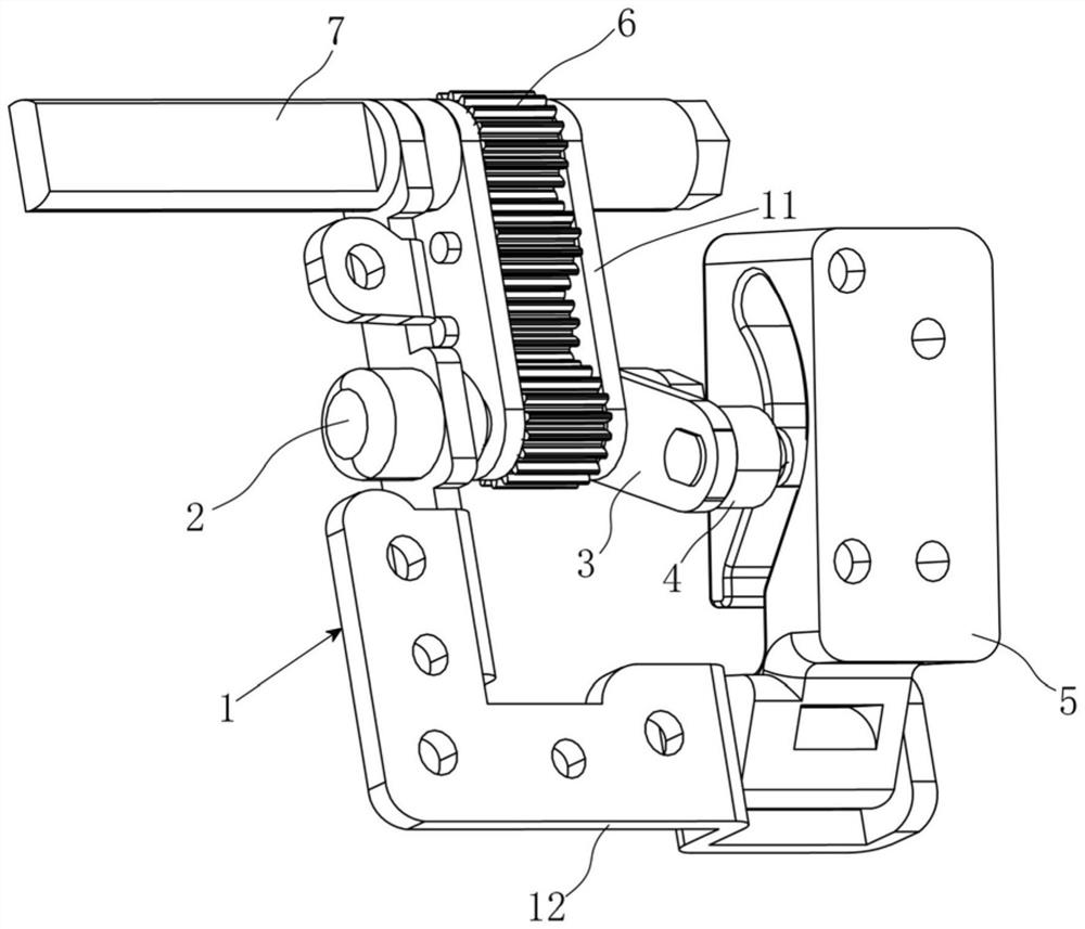
[0004] Therefore, the technical problem to be solved by the present invention is to overcome the defect that the notebook computer feet need to be deliberately operated and inconvenient to use in the prior art, so as to provide a foot pad linkage mechanism that can extend the foot pads when the computer cover is opened.

Method used


Image

  • Foot pad linkage mechanism and notebook computer
  • Foot pad linkage mechanism and notebook computer
  • Foot pad linkage mechanism and notebook computer

Examples


Embodiment Construction

[0051] The technical solutions of the present invention will be clearly and completely described below in conjunction with the accompanying drawings. Apparently, the described embodiments are some of the embodiments of the present invention, but not all of them. Based on the embodiments of the present invention, all other embodiments obtained by persons of ordinary skill in the art without making creative efforts belong to the protection scope of the present invention.

[0052] In describing the present invention, it should be noted that the terms "center", "upper", "lower", "left", "right", "vertical", "horizontal", "inner", "outer" etc. indicate The orientation or positional relationship is based on the orientation or positional relationship shown in the drawings, and is only for the convenience of describing the present invention and simplifying the description, rather than indicating or implying that the referred device or element must have a specific orientation or be conf...


PUM


Abstract

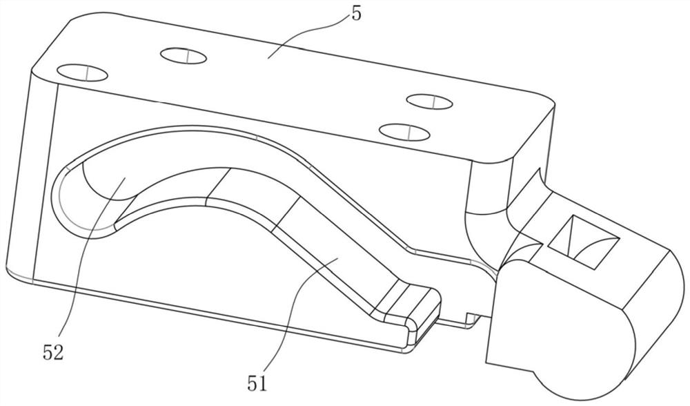
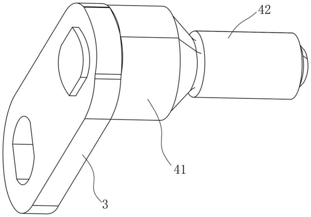
The invention relates to the technical field of supporting foot pads, in particular to a foot pad linkage mechanism and a notebook computer. Comprising a fixing frame; the rotating shaft is rotationally mounted on the fixing frame; one end of the rotating cantilever is fixed on the rotating shaft; the universal driving shaft is located at the other end of the rotating cantilever, and the universal driving shaft and the rotating cantilever are fixedly connected or integrally formed or rotationally connected; the rotating block is suitable for installing a foot pad, the rotating block is located on the side, in the direction where the rotating shaft is located, of the rotating cantilever and located on the same side as the linkage shaft, the rotating block is rotationally connected to the fixing frame, the rotating axis of the rotating block is parallel to the rotating shaft, a linkage groove / hole is formed in the surface, close to the rotating cantilever, of the rotating block, and the linkage shaft is arranged in the linkage groove / hole; the linkage groove / hole is suitable for realizing unidirectional rotation of the rotating block when the rotating shaft rotates unidirectionally; the transmission assembly is suitable for achieving synchronous rotation of the hinged shaft and the rotating shaft of the product. According to the foot pad linkage mechanism, the hinge shaft and the foot pad can be linked to act, operation is convenient, and the appearance requirement is met.

Description

technical field [0001] The invention relates to the technical field of supporting foot pads, in particular to a foot pad linkage mechanism and a notebook computer. Background technique [0002] There are many products in life, which are composed of two parts, and the two parts are hinged by hinges located at the edges. Some of these products are provided with foot pads at the bottom to play a supporting role. For example, a notebook computer is provided with foot pads on the rear side of the bottom to achieve support and increase the height of the rear side of the notebook through the foot pads to ensure heat dissipation. [0003] Existing notebook computers generally fix the foot pads directly on the bottom. If it is necessary to increase the height of the foot pads to improve the air intake efficiency of the fan, the thickness of the foot pads can only be simply increased, so that the notebook looks bulky and damaged. The aesthetics of the notebook. There is also a Push...

Claims


Application Information

Patent Timeline
Patent Type & Authority Applications(China)
IPC IPC(8): G06F1/16
CPCG06F1/1622
Inventor 王兴磊周堂法张辉谭道常甘立渊
Owner 紫光计算机科技有限公司
Learn More