
River channel environment dehumidification device for water conservancy project

A technology for water conservancy projects and river channels, applied in the use of liquid separation agents, gas treatment, membrane technology, etc., can solve problems such as affecting the health of residents, residents' discomfort, and rheumatism, to improve the dehumidification effect, facilitate protection, improve The effect of adsorption capacity

Pending Publication Date: 2022-03-25
董高娃
View PDF6 Cites 0 Cited by
  • Summary
  • Abstract
  • Description
  • Claims
  • Application Information

AI Technical Summary

Problems solved by technology

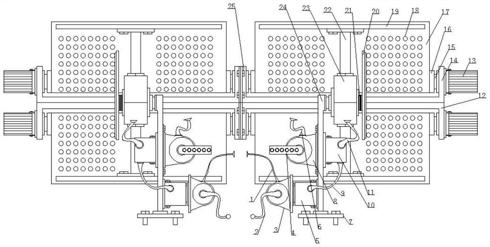
[0002] Residents living near rivers tend to be in a humid environment for a long time, especially at night. Residents near rivers are more likely to be in a humid environment. For rural bungalows, they are more affected by moisture. , Residents in a humid environment for a long time will suffer from rheumatism, etc., which will affect the health of residents. During the day, due to the existence of sunlight, the evaporation of moisture is accelerated, and the impact on residents is not great. At night, especially In addition, the blowing of the cold wind will make the nearby residents feel uncomfortable. The inventor thought that it would be good if the residents around the river can be dehumidified at night, so the inventor invented a kind of Water conservancy projects use the river environment dehumidification device to solve the dehumidification problem of the river environment

Method used


Image

  • River channel environment dehumidification device for water conservancy project
  • River channel environment dehumidification device for water conservancy project

Examples


Embodiment Construction

[0016] The following will clearly and completely describe the technical solutions in the embodiments of the present invention with reference to the accompanying drawings in the embodiments of the present invention. Obviously, the described embodiments are only some, not all, embodiments of the present invention. Based on the embodiments of the present invention, all other embodiments obtained by persons of ordinary skill in the art without making creative efforts belong to the protection scope of the present invention.

[0017] see Figure 1-2 , the present invention provides a technical solution:

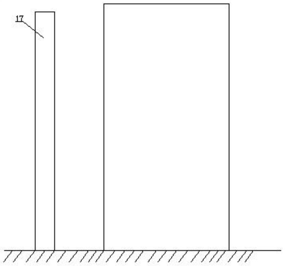
[0018] A river environment dehumidification device for water conservancy projects, comprising a symmetrically arranged bottom plate 7, a symmetrically arranged first frame 12 and a second frame 14, the upper surface of the bottom plate 7 is welded with a support rod 24, and the inside of the support rod 24 A material storage box 5 is fixedly installed on the lower side of the side...


PUM


Abstract

The riverway environment dehumidification device for the water conservancy project comprises symmetrically-arranged bottom plates, a first clamping frame and a second clamping frame, the first clamping frame and the second clamping frame are symmetrically arranged, supporting rods are welded to the upper surfaces of the bottom plates, and a storage box is fixedly installed on the lower side of the inner side face of each supporting rod; a water pump is fixedly installed on the surface of the material storage box, the liquid inlet end of the water pump is connected with a second connecting pipe, the liquid outlet end of the water pump is connected with a first connecting pipe, a draught fan fixedly connected with the supporting rod is arranged above the material storage box, the air inlet end of the draught fan is connected with a ventilation pipe, and the air outlet end of the draught fan is connected with a third connecting pipe. A material pump is fixedly installed on the upper side of the outer surface of the supporting rod, and a fourth connecting pipe is connected between the material pump and the material storage box. By controlling the shielding cloth, the adsorption capacity to the humid environment around the river channel can be improved, and then residents around the river channel can be protected conveniently.

Description

technical field [0001] The invention relates to the field of water conservancy engineering, in particular to a river course environment dehumidification device for water conservancy engineering. Background technique [0002] Residents living near rivers tend to be in a humid environment for a long time, especially at night. Residents near rivers are more likely to be in a humid environment. For rural bungalows, they are more affected by moisture. , Residents in a humid environment for a long time will suffer from rheumatism, etc., which will affect the health of residents. During the day, due to the existence of sunlight, the evaporation of moisture is accelerated, and the impact on residents is not great. At night, especially In addition, the blowing of the cold wind will make the nearby residents feel uncomfortable. The inventor thought that it would be good if the residents around the river can be dehumidified at night, so the inventor invented a kind of Water conservanc...

Claims


Application Information

Patent Timeline
Patent Type & Authority Applications(China)
IPC IPC(8): B01D53/26B01D47/06
CPCB01D53/261B01D47/06B01D2257/80
Inventor 董高娃
Owner 董高娃
Learn More