Material screening equipment for constructional engineering

A screening equipment and construction engineering technology, applied in the direction of sieve, solid separation, grille, etc., can solve the problems of causing respiratory diseases, low efficiency of manual screening of materials, easy and incomplete screening, etc., and achieve the effect of high-efficiency screening of materials

Pending Publication Date: 2022-03-25
朱亚凤
View PDF19 Cites 2 Cited by
  • Summary
  • Abstract
  • Description
  • Claims
  • Application Information

AI Technical Summary

Problems solved by technology

[0003] However, the screening of construction waste in the prior art usually adopts the method of manual screening. Workers are in close contact with the screening environment, which is likely to cause respiratory diseases due to excessive adsorption of waste dust. Moreover, the efficiency of manual screening of materials is low, and it is easy to be incompletely screened and affect subsequent classification. processing; therefore, the present invention provides a kind of material screening equipment for construction engineering, to solve the above problems

Method used


Image

  • Material screening equipment for constructional engineering
  • Material screening equipment for constructional engineering
  • Material screening equipment for constructional engineering

Examples


Embodiment 1

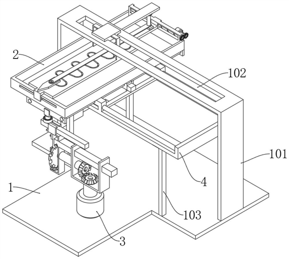
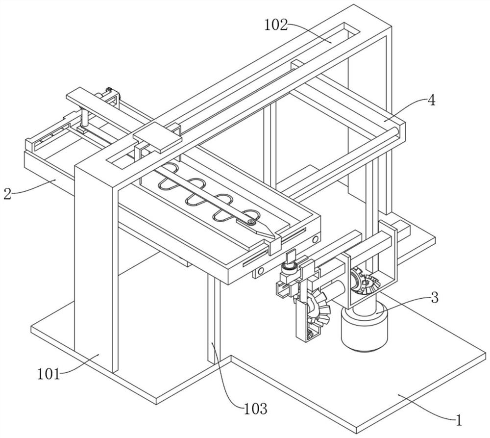
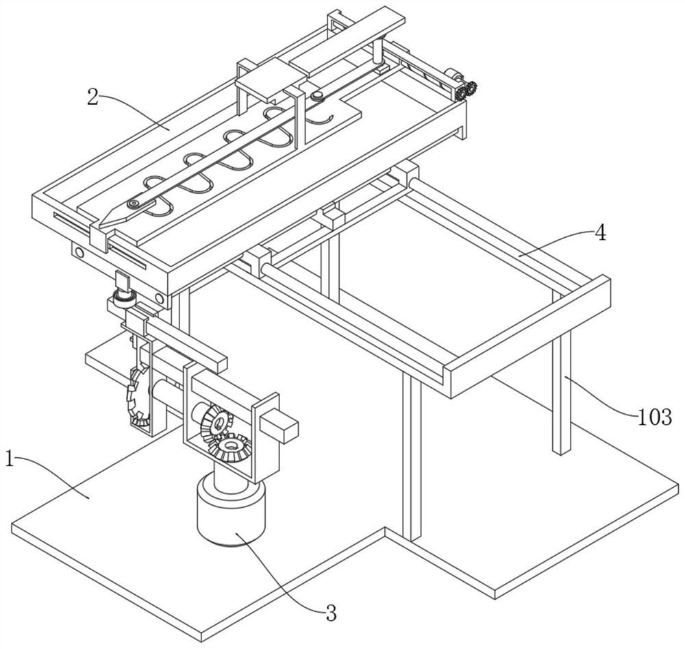
[0035] see Figure 1-7 , a material screening device for construction engineering, comprising a mounting base 1, a vertical frame 101 is fixedly connected to both sides above the mounting base 1, a sieve material frame 2 is slidably connected to the bottom of the vertical frame 1, and the sieve material frame 2 is slidably connected to a traverse frame 4, the lower side of the traverse frame 4 is fixedly connected to the upper side of the installation base 1 through the column 103, and one end of the upper side of the installation base 1 is provided with a transmission mechanism 3, and the upper end of the transmission mechanism 3 is movably connected with the screening frame 2;

[0036] Both sides above the traverse frame 4 are fixedly connected with a slide bar A401, the slide bar A401 is slidably connected with a drive frame 402, and the center of the drive frame 402 is slidably connected with a beam 404; both sides of the beam 404 are fixedly connected with a slide bar B403...

Embodiment 2

[0039] see Figure 7-8, based on Example 1, the difference is that:

[0040] Both ends of the lower side of the sieve frame 2 are fixedly connected to two side plates 405 respectively, and a track board 201 is movably connected to the top of the sieve frame 2, and a swing rail 202 is provided on the track board 201; a drive column is slidingly connected to the center of the swing rail 202, The upper end of the drive column is movably connected with a swing block 208, which is slidably connected to the upper side of the swing rail 202, and the lower end of the drive column is movably connected with a stirring block 209 through a torsion spring;

[0041] The upper side of the swing block 208 is rotatably connected with a linkage rod 203, and the end of the linkage rod 203 is rotatably connected with a transmission rod 206; The outer sides of the frame 101 slide against each other; the upper sides of the track plate 201 are fixedly connected with a fixed frame 204, and the cente...

Embodiment 3

[0046] see Figure 9-10 , based on Embodiment 1 and 2, the difference is that:

[0047] The transmission mechanism 3 includes a motor C301, which is fixedly connected to the installation base 1. The upper end of the output shaft of the motor C301 is fixedly connected with a conical wheel A303; One side is meshed with a conical wheel B304, and the axis of the conical wheel B304 is fixedly connected with a conical wheel C306 through the transmission shaft 305;

[0048] The outer end of the transmission shaft 305 is movably connected with a U-shaped frame B312, the upper end of the U-shaped frame A302 is fixedly connected with the U-shaped frame B312 through a connecting rod 307, and the upper end of the U-shaped frame B312 is rotatably connected with a cone wheel D311, and the axis of the cone wheel D311 The sliding sleeve block 310 is fixedly connected with the connecting column 313;

[0049] The sliding sleeve 310 is slidingly connected with a gear lever 308, and the gear le...


PUM


Abstract

The invention discloses material screening equipment for constructional engineering, and belongs to the technical field of constructional engineering. Material screening equipment for constructional engineering comprises a mounting base, vertical frames are fixedly connected to the two sides of the upper portion of the mounting base, a material screening frame is slidably connected to the lower portions of the vertical frames, the material screening frame is slidably connected to a transverse moving frame, and the lower side of the transverse moving frame is fixedly connected to the upper side of the mounting base through stand columns; a transmission mechanism is arranged at one end of the upper side of the mounting base, and the upper end of the transmission mechanism is movably connected with the screening frame; sliding rods A are fixedly connected to the two sides of the upper portion of the transverse moving frame, a transmission frame is slidably connected to the sliding rods A, and a cross beam is slidably connected to the center of the transmission frame; sliding rods B are fixedly connected to the two sides of the cross beam, the two ends of the sliding rods B are fixedly connected through side plates, and the sliding rods B are slidably connected into the transmission frame; the problem that in the prior art, a manual screening mode is low in efficiency is solved.

Description

technical field [0001] The invention relates to the technical field of construction engineering, in particular to material screening equipment for construction engineering. Background technique [0002] Construction waste refers to the dregs, spoils, waste materials, residual mud and other wastes generated during the construction, laying or demolition and repair of various buildings, structures, pipe networks, etc. by construction units or individuals; These construction wastes are of no help to the construction itself, but they are substances produced during the construction process, which need to be treated accordingly, so as to achieve the ideal project construction; some construction wastes are large in size and require It is dried and crushed before transportation, and the construction waste is crushed into small particle materials, which are then screened and classified for further classification. [0003] However, the screening of construction waste in the prior art ...

Claims


Application Information

Patent Timeline
Patent Type & Authority Applications(China)
IPC IPC(8): B07B1/28B07B1/42B07B1/46
CPCB07B1/28B07B1/42B07B1/46
Inventor 朱亚凤
Owner 朱亚凤
Why Eureka
Try Eureka