Supercharge Your Innovation With Domain-Expert AI Agents!

Oscillation type test tube cleaning device

A technology for cleaning devices and test tubes, which is applied in the direction of cleaning hollow objects, laboratory cleaning equipment, cleaning methods and utensils, and can solve the problems of prolonging the time required for cleaning the inner wall of test tubes, incomplete cleaning of massive particle attachments, and low operating efficiency. problems, to achieve the effect of eliminating residues of attachments, eliminating potential safety hazards, and cleaning thoroughly

Inactive Publication Date: 2022-03-25
柯伟超
View PDF0 Cites 0 Cited by
  • Summary
  • Abstract
  • Description
  • Claims
  • Application Information

AI Technical Summary

Problems solved by technology

[0005] The purpose of the present invention is to provide an oscillating test tube cleaning device. When the present invention is used, the support sleeve is first fixed on the driving part, and then the rotating rod body is connected with the output shaft of the driving part, and the output shaft of the driving part rotates to drive the rotating rod body. Rotating, the rotating rod drives the cleaning sheet to swing back and forth through the pulling mechanism to clean the inner wall of the test tube, so as to solve the incomplete cleaning of massive particle attachments and the existence of attachment residues; manual cleaning has certain safety hazards; the operation efficiency is low, and the cleaning of the inner wall of the test tube is prolonged. question of time required

Method used


Image

  • Oscillation type test tube cleaning device
  • Oscillation type test tube cleaning device
  • Oscillation type test tube cleaning device

Examples


Embodiment Construction

[0037] The present invention will be further described below in conjunction with the accompanying drawings.

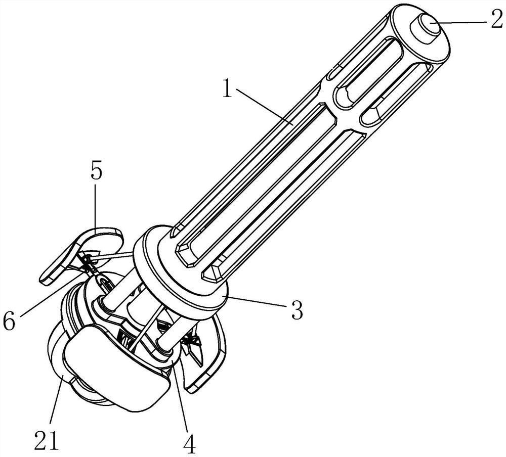
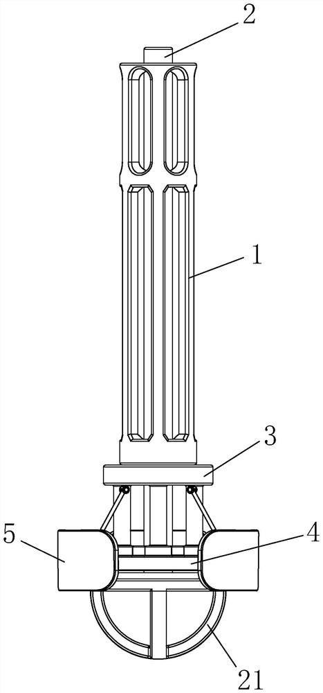
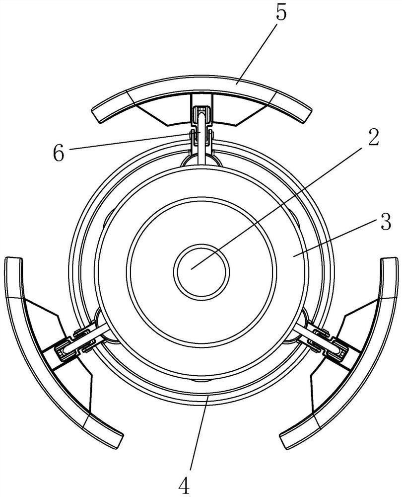
[0038] Such as figure 1 , 2 The oscillating test tube cleaning device shown includes a support sleeve 1 and a rotating rod body 2 located inside the support sleeve 1. The axes of the support sleeve 1 and the rotating rod body 2 coincide, wherein the support sleeve 1 is a long strip structure with an inner cavity. When used, such as Figure 13 As shown, the support sleeve 1 is fixed on the driving part 7, and the top end of the rotating rod body 2 and the output shaft of the driving part 7 are connected together through a coupling, and then the support sleeve 1 is inserted into the inside of the test tube 8, and the driving part The rotation of the output shaft of 7 drives the rotating rod body 2 to rotate to provide the power required for cleaning. The support sleeve 1 is used to stably support the rotating rod body 2 to prevent the free end of the rotating rod body ...


PUM


Abstract

The invention discloses an oscillation type test tube cleaning device which comprises a supporting sleeve and a rotating rod body located in the supporting sleeve, the axis of the supporting sleeve coincides with the axis of the rotating rod body, a first fixing piece and a second fixing piece are arranged at the bottom end of the supporting sleeve, and a preset distance is reserved between the first fixing piece and the second fixing piece in the direction of the supporting sleeve. A cleaning piece is movably arranged on the edge of the second fixing piece, a pulling mechanism is arranged between the first fixing piece and the cleaning piece, and the pulling mechanism can pull the cleaning piece to swing up and down. The pulling mechanism comprises a polarization ring, an ejector head, a pull rod, a sliding seat and a mounting seat, the polarization ring is fixed to the rotating rod body and located in the first fixing piece, and the ejector head is arranged in an ejector head sliding cavity in the first fixing piece in a sliding mode. The cleaning effect can be improved, and waste liquid is prevented from remaining on the inner wall of the test tube; the cleaning efficiency is improved, and the cleaning operation time is shortened.

Description

technical field [0001] The invention relates to the technical field of test tube cleaning, in particular to an oscillating test tube cleaning device. Background technique [0002] A test tube is a common container for chemical reactions with a small amount of reagents, and is mainly used in pharmaceutical research and chemical laboratories. The test tube can be used in both normal temperature and heating environments. If heating is required, the test tube needs to be preheated before heating, so that the test tube can be heated evenly and used safely. There are also many types and specifications of test tubes. Specifically, they can be divided into ordinary test tubes, support test tubes, and centrifuge test tubes. [0003] On the other hand, some common combustion experiments can be carried out in test tubes, such as potassium permanganate heating to oxygen production, red phosphorus combustion and other experiments. During the experiment, the burning chemical reagents fo...

Claims


Application Information

Patent Timeline
Patent Type & Authority Applications(China)
IPC IPC(8): B08B9/087B08B7/02B08B13/00B01L99/00
CPCB08B9/0808B08B7/02B08B13/00B08B9/0817B08B9/0821B01L13/02B01L99/00
Inventor 柯伟超
Owner 柯伟超
Features
  • R&D
  • Intellectual Property
  • Life Sciences
  • Materials
  • Tech Scout
  • Unparalleled Data Quality
  • Higher Quality Content
  • 60% Fewer Hallucinations
Learn More