
relief valve

A technology for relief valves and slide valves, which is applied in the direction of safety valves, balance valves, valve devices, etc., and can solve the problem of inability to close the valve core of the slide valve, damage the pressure setting function of the relief valve, and the inability to stably control the pressure oil pressure and other problems to achieve the effect of suppressing the residual pressure

Active Publication Date: 2018-05-11
NIHON KENKI CO LTD
View PDF5 Cites 0 Cited by
  • Summary
  • Abstract
  • Description
  • Claims
  • Application Information

AI Technical Summary

Problems solved by technology

[0008] If a foreign matter is bitten between the above-mentioned displacement restricting part and the spool valve core, the spool valve core cannot be completely closed.
Therefore, the pressurized oil in the hydraulic circuit leaks to the tank port side of the relief valve, and the pressure of the pressurized oil cannot be stably controlled.
In addition, the foreign matter bitten once will not be discharged by the flow of oil, but will remain in a state of adhering between the above-mentioned displacement restricting part and the spool valve element, and may damage the pressure setting function of the relief valve. sex

Method used


Image

  • relief valve
  • relief valve
  • relief valve

Examples


Embodiment Construction

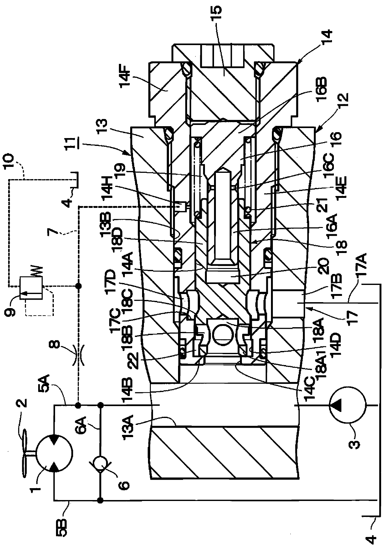
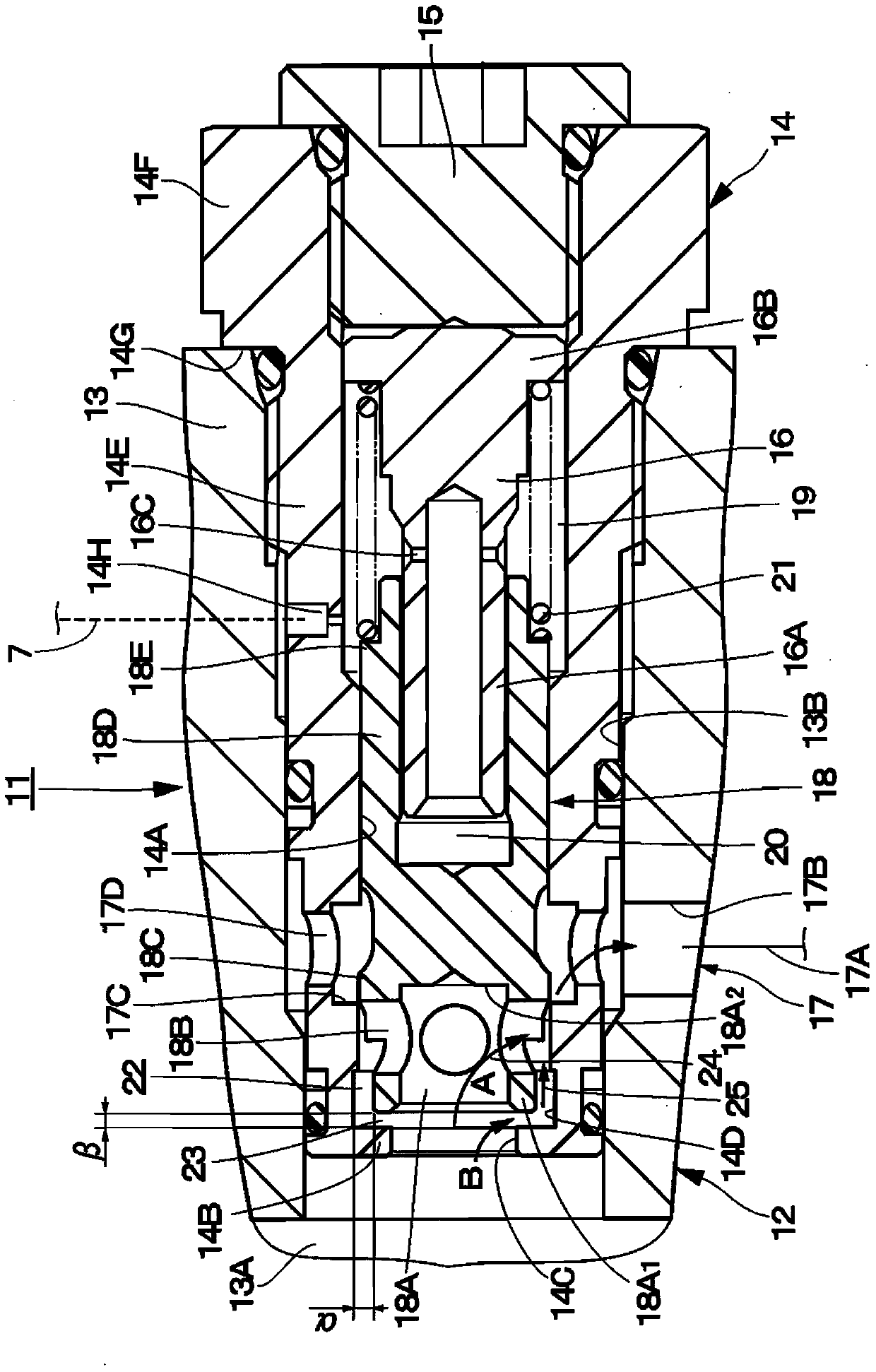
[0030] Below, refer to Figure 1 to Figure 6 The accompanying drawings will describe the relief valve in detail by taking the case where the relief valve according to the embodiment of the present invention is used in a drive circuit of a fan motor as an example.

[0031] here, figure 1 as well as figure 2 The first embodiment of the present invention is shown. In the figure, 1 is a fan motor as a hydraulic transmission device, and the fan motor 1 is composed of a hydraulic motor, and drives the cooling fan 2 to rotate. A construction machine represented by a hydraulic excavator is provided with heat exchangers such as a radiator for cooling engine cooling water and an oil cooler for cooling working oil (none of which are shown), and the cooling fan 2 supplies heat to the heat exchanger. cooling wind.

[0032]In addition, the heat exchanger provided in the construction machine is not limited to the above-mentioned radiator and oil cooler, and may include, for example, an ...


PUM


Abstract

A spool valve body (18) has an axial one side provided with a pressure receiving part (18A), one side of which opens and the other side of which closes, for receiving pressures in said supply passage (13A), and a radial hole (18B) that radially communicates an inside and an outside of the pressure receiving part (18A). An annular gap (22) for the hydraulic oil to flow therein at the opening of the spool valve body (18) is formed between an inner peripheral surface of one side of the spool sliding bore (14A) adjacent to the displacement regulating part (14B) and an outer periphery of the peripheral wall of the pressure receiving part (18A). At the opening of the spool valve body (18), a first oil passage (24) in which the hydraulic oil flows to the tank port (17) from the supply passage (13A) through the pressure receiving part (18A) and the radial hole (18B) and a second oil passage (25) in which the hydraulic oil flows to the tank port (17) through the axial gap (23) and the annular gap (22) between the displacement regulating part (14B) and the spool valve body (18), are formed.

Description

technical field [0001] The present invention relates to a relief valve suitable for use in hydraulic equipment such as construction machinery. Background technique [0002] Generally, a construction machine represented by a hydraulic excavator is equipped with a relief valve in order to suppress the occurrence of excess pressure in a hydraulic circuit due to breakage or damage of hydraulic equipment. Such a conventional relief valve is configured to open the valve when excess pressure is generated to release the excess pressure to the tank side. In addition, as such a relief valve, there is known a structure in which a spool sliding hole is provided in the valve case, and a spool valve element fitted in the spool sliding hole is slid and displaced in the axial direction to thereby displace the spool valve. The above-mentioned residual pressure is released to the tank side (for example, refer to Patent Documents 1 and 2). [0003] prior art literature [0004] patent docum...

Claims


Application Information

Patent Timeline
Patent Type & Authority Patents(China)
IPC IPC(8): F16K17/06
CPCF15B13/024F16K17/06
Inventor 安藤真和吉本光宏伊东英明泷口和夫高尾昌希
Owner NIHON KENKI CO LTD
Features
  • Generate Ideas
  • Intellectual Property
  • Life Sciences
  • Materials
  • Tech Scout
  • Unparalleled Data Quality
  • Higher Quality Content
  • 60% Fewer Hallucinations
Learn More