Piezoelectric pulse propeller with high mass flow and underwater robot

An electric pulse and thruster technology, applied in ship propulsion, propulsion components, ship construction, etc., can solve the problems of insufficient mass flow, unidirectional fluid motion, and high heat loss, and reduce the frequency of atomic dislocation motion. Effect of surface area and volume, heat loss reduction

Active Publication Date: 2022-03-25
HANGZHOU DIANZI UNIV
View PDF21 Cites 0 Cited by
  • Summary
  • Abstract
  • Description
  • Claims
  • Application Information

AI Technical Summary

Problems solved by technology

However, in order to realize the piezoelectric pulse thruster, the traditional design will encounter three problems: one is the one-way movement of the fluid, the other is the high heat loss during the working process, and the third is the mass flow rate is not large enough
The dislocation movement of atoms in the vibrator polycrystal caused by bending or deflection will continue to generate heat, resulting in a large heat loss

Method used


Image

  • Piezoelectric pulse propeller with high mass flow and underwater robot
  • Piezoelectric pulse propeller with high mass flow and underwater robot
  • Piezoelectric pulse propeller with high mass flow and underwater robot

Examples


Embodiment 1

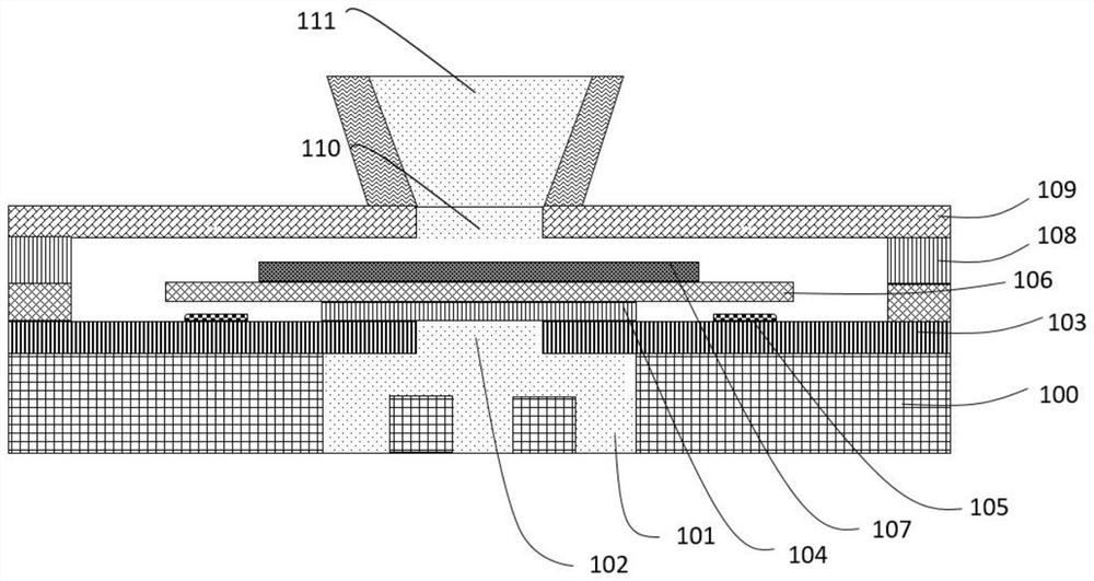
[0036] Such as figure 1 As shown, a high-quality flow piezoelectric pulse impeller includes an inflow layer 100, a composite alloy layer 103, a vibration substrate layer 106, a vibration layer 107, an upper electrode layer 108 and a shell layer 109 stacked in sequence, and The plugging layer 104 and the O-ring 105 are located between the composite alloy layer 103 and the vibrating substrate layer 106 .

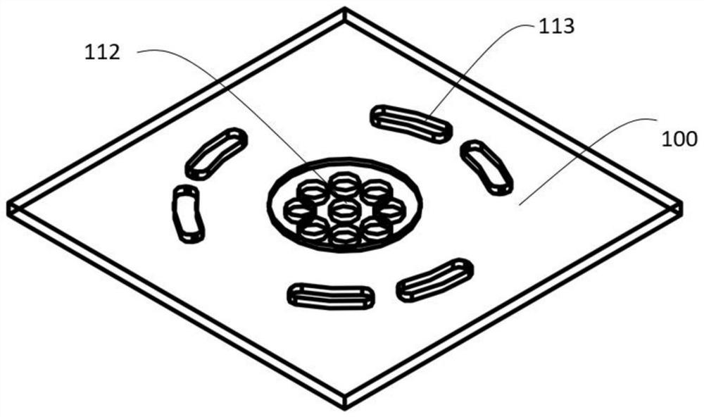
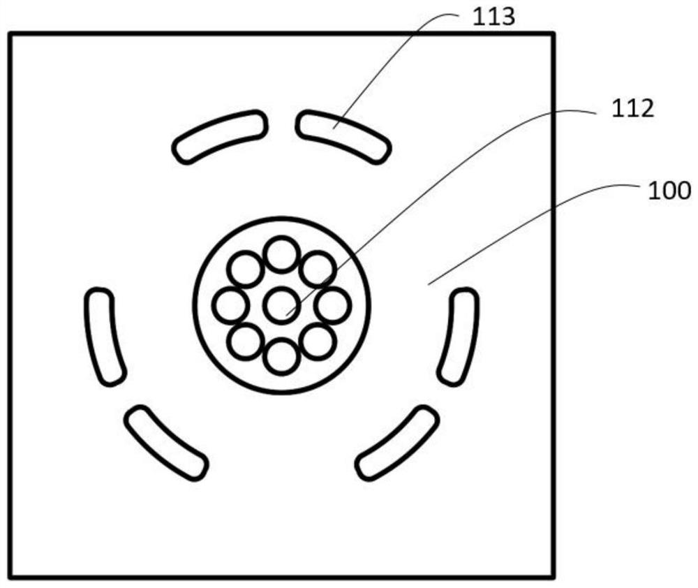
[0037] Such as figure 2 and 3As shown, a first flow channel 101 is opened on the inflow layer 100 ; a second flow channel 102 is opened on the composite alloy layer 103 . The first flow path 101 and the second flow path 102 are butted together to form an input flow path. The first flow channel 101 includes a flow cavity and nine liquid inlets. Each liquid inlet is in communication with the flow cavity; the flow cavity is in communication with the second flow path 102 .

[0038] The vibrating substrate layer 106 includes an edge fixing part, a connecting piece 116 and a c...

Embodiment 2

[0066] An underwater robot is equipped with one or more piezoelectric pulse thrusters as described in Embodiment 1 at the tail; by controlling the input voltage and frequency of the piezoelectric pulse thrusters, the propulsion force of the piezoelectric pulse thrusters can be adjusted.


PUM


Abstract

The invention discloses a piezoelectric pulse propeller with high mass flow and an underwater robot. The pusher comprises an inflow layer, a composite alloy layer, a vibration substrate layer, a vibration layer, an upper electrode layer and a shell layer which are sequentially stacked, and a blocking layer and an O-shaped sealing ring which are located between the composite alloy layer and the vibration substrate layer. A gap between the O-shaped sealing ring and the blocking layer forms a variable pressure chamber; according to the invention, when the piezoelectric vibrator performs negative displacement, the radial edge of the vibrator is firstly tightly attached to the sealing ring, the volume of the variable-pressure chamber is increased, and fluid is sucked due to negative pressure; when the piezoelectric vibrator moves positively, the center of the vibrator is firstly tightly attached to the inflow hole of the composite alloy layer, the radial edge of the vibrator is far away from the sealing ring, fluid in the variable-pressure cavity is forced to enter the output flow channel, the fluid lost by the output flow channel when the piezoelectric vibrator moves negatively is supplemented, and fluid is provided for next spraying; and high-frequency vibration is carried out in cycles, so that pulse injection of the fluid is realized, and one-way high-quality flow conveying of the fluid is realized.

Description

technical field [0001] The invention belongs to the technical field of micro underwater drives, and in particular relates to a piezoelectric thruster using a petal-shaped piezoelectric material and a superelastic nickel-titanium composite metal substrate and a preparation method thereof, which can be applied to the propulsion of a micro robot. Background technique [0002] Traditional underwater propulsion has always been dominated by rotary propulsion, such as propeller propulsion, pump jet propulsion (which also uses high-speed rotation of the blade to inhale fluid and then eject it) and so on. The conventional propeller has the disadvantages of complex structure, severe wear, and relatively low efficiency due to lateral force. Also due to the existence of relative rotation, it is also very difficult to process in terms of miniaturization and integration. Based on this, subsequent scholars and engineers have also proposed non-rotating propulsion methods such as flapping w...

Claims


Application Information

Patent Timeline
Patent Type & Authority Applications(China)
IPC IPC(8): B63H11/02
CPCB63H11/02B63H2011/004B63H2011/006
Inventor 李懿霖倪嘉锋王佳斌轩伟鹏朱慕尧李文钧
Owner HANGZHOU DIANZI UNIV
Why Eureka
Try Eureka