
Laser cladding powder feeding equipment

A technology of laser cladding and powder feeding, which is applied in the coating process and coating of metal materials, and can solve the problems of powder instability and deviation

Active Publication Date: 2022-03-25
NANJING HUIRUI PHOTOELECTRIC TECH CO LTD
View PDF6 Cites 0 Cited by
  • Summary
  • Abstract
  • Description
  • Claims
  • Application Information

AI Technical Summary

Problems solved by technology

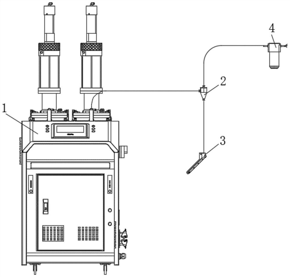
[0004] The purpose of the present invention is to provide a laser cladding powder feeding equipment, which converts the carrier gas powder feeding method into the gravity powder feeding method, which not only avoids the technical problem of flowing gas blowing away the powder on the surface of the workpiece in the carrier gas powder feeding method, Moreover, the mechanical arm does not need to carry a heavy powder feeder, which solves the problem of powder instability and deviation when the powder nozzle is discharged due to the shaking of the powder feeding pipe caused by the movement of the mechanical arm, and improves the cladding quality and efficiency.

Method used


Image

  • Laser cladding powder feeding equipment
  • Laser cladding powder feeding equipment
  • Laser cladding powder feeding equipment

Examples


Embodiment Construction

[0024] In order to make the technical problems, technical solutions and beneficial effects to be solved by the present invention clearer, the present invention will be further described in detail below in conjunction with the accompanying drawings and embodiments. It should be understood that the specific embodiments described here are only used to explain the present invention, not to limit the present invention.

[0025] It should be noted that when an element is referred to as being “fixed” or “disposed on” another element, it may be directly on the other element or be indirectly on the other element. When an element is referred to as being "connected to" another element, it can be directly connected to the other element or indirectly connected to the other element.

[0026] In addition, the terms "first" and "second" are used for descriptive purposes only, and cannot be interpreted as indicating or implying relative importance or implicitly specifying the quantity of indic...


PUM


Abstract

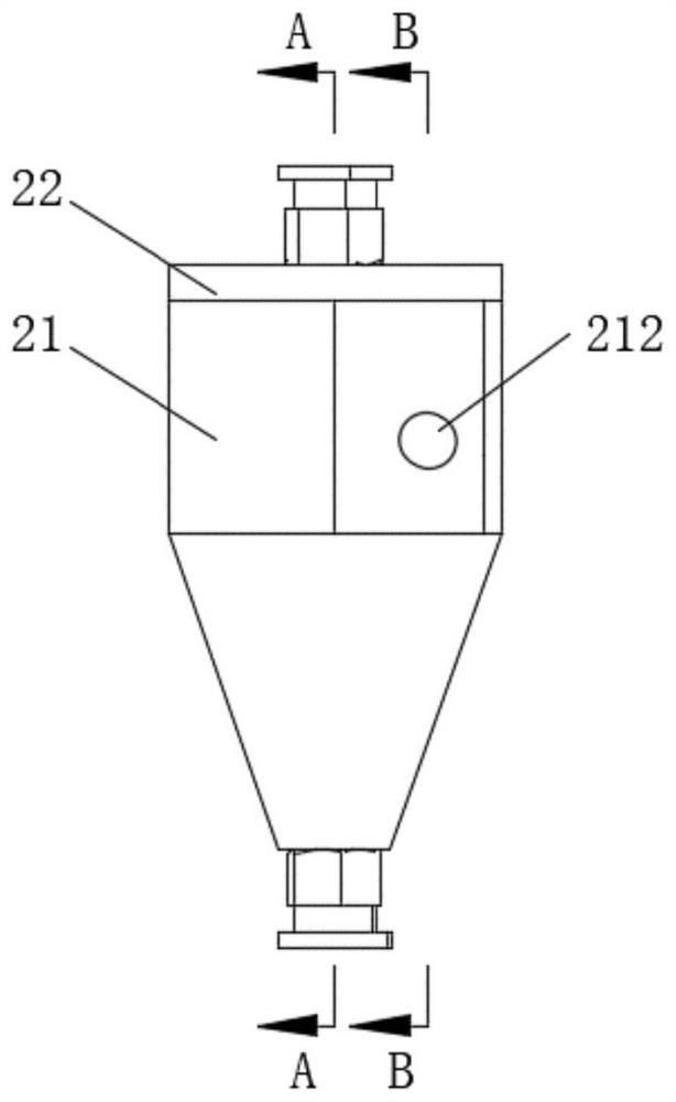
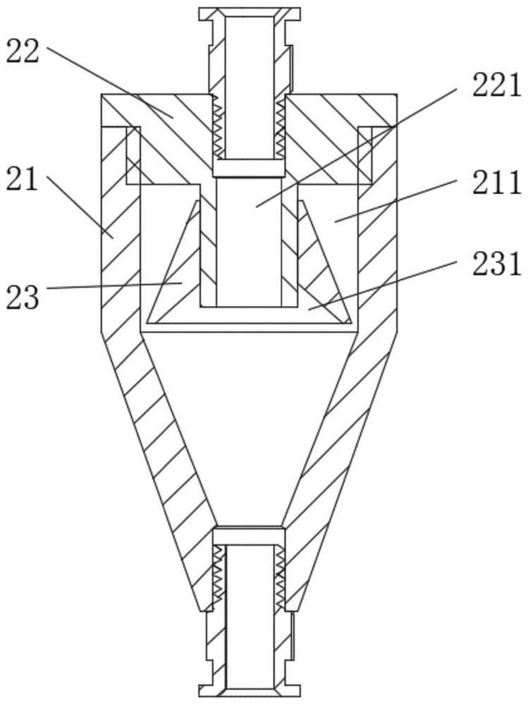
The invention discloses laser cladding powder feeding equipment and relates to the technical field of laser cladding, a carrier gas powder feeding mode is converted into a gravity powder feeding mode, the technical problem that flowing gas blows away powder on the surface of a workpiece in the carrier gas powder feeding mode is avoided, a mechanical arm does not need to bear a heavy powder feeder, and the powder feeding efficiency is improved. The phenomena that when the mechanical arm moves, the powder feeding pipe shakes, and consequently powder is unstable and deviates when the powder feeding nozzle discharges powder are avoided, and the cladding quality and efficiency are improved. The laser cladding powder feeding equipment comprises a powder supply unit, a separation unit and a powder feeding nozzle, wherein the powder supply unit is used for providing carrier gas powder. The separation unit communicates with the powder supply unit and is used for receiving the carrier gas powder and separating gas and powder of the carrier gas powder. And the powder feeding nozzle is communicated with the separating unit, is used for receiving the separated powder and gathering the powder on the surface of the workpiece, and is positioned below the separating unit.

Description

technical field [0001] The invention relates to the technical field of laser cladding, in particular to a powder feeding equipment for laser cladding. Background technique [0002] Laser cladding technology is a new workpiece surface modification technology that has emerged with the development of high-power lasers. It adds cladding materials (usually powder) to the surface of the workpiece through laser cladding powder feeding nozzles, and uses high energy density. The laser beam is used to fuse it with the thin layer on the surface of the workpiece to form a metallurgically bonded cladding layer on the surface of the workpiece. The additive cladding layer can significantly improve the properties of the workpiece surface such as wear resistance, corrosion resistance, heat resistance, and oxidation resistance. [0003] In the prior art, there are mainly two methods of powder feeding in laser cladding processing. One is carrier gas powder feeding, which uses gas flow to carr...

Claims


Application Information

Patent Timeline
Patent Type & Authority Applications(China)
IPC IPC(8): C23C24/10
CPCC23C24/10Y02P10/25
Inventor 谢寿春黄河陶鸣邓小松
Owner NANJING HUIRUI PHOTOELECTRIC TECH CO LTD
Learn More