Water suction pump with heating mechanism
A technology of heating mechanism and water suction pump, which is applied to the components, pump components, mechanical equipment, etc. of the pumping device for elastic fluid, which can solve the problem of fast pumping speed of water pump, unusable water pump, damage of impact heater parts, etc. question
- Summary
- Abstract
- Description
- Claims
- Application Information
AI Technical Summary
Problems solved by technology
Method used
Image

Examples
Embodiment 1
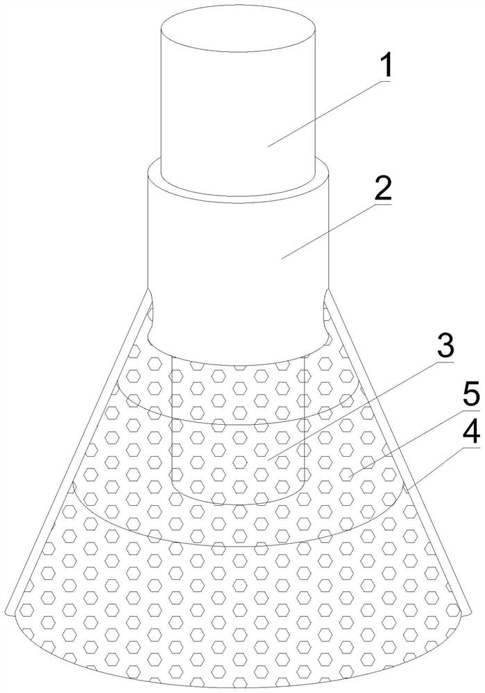
[0037] like Figure 1-7 As shown, the present invention provides a water suction pump with its own heating mechanism, comprising a water suction pump 1, an outer protective shell 2, a water suction pipe head 3, a support frame bar 4 and a filter screen 5, and the outer surface of the water suction pump 1 is detachable The jacket protective shell 2 is installed, the output end of the water suction pump 1 is provided with a suction pipe head 3, the outer surface of the bottom of the outer jacket protective shell 2 is fixedly connected with a support frame bar 4, and the outer surface of the support frame bar 4 is provided with a filter net 5.
[0038] In this embodiment, the water suction pipe head 3 is sucked through the water suction pump 1, and the outer surface of the water suction pump 1 is protected with the outer protective shell 2, and then the outer surface of the outer protective shell 2 is protected by the support frame bar 4. Unfold, utilize filter net 5 to filter t...
Embodiment 2
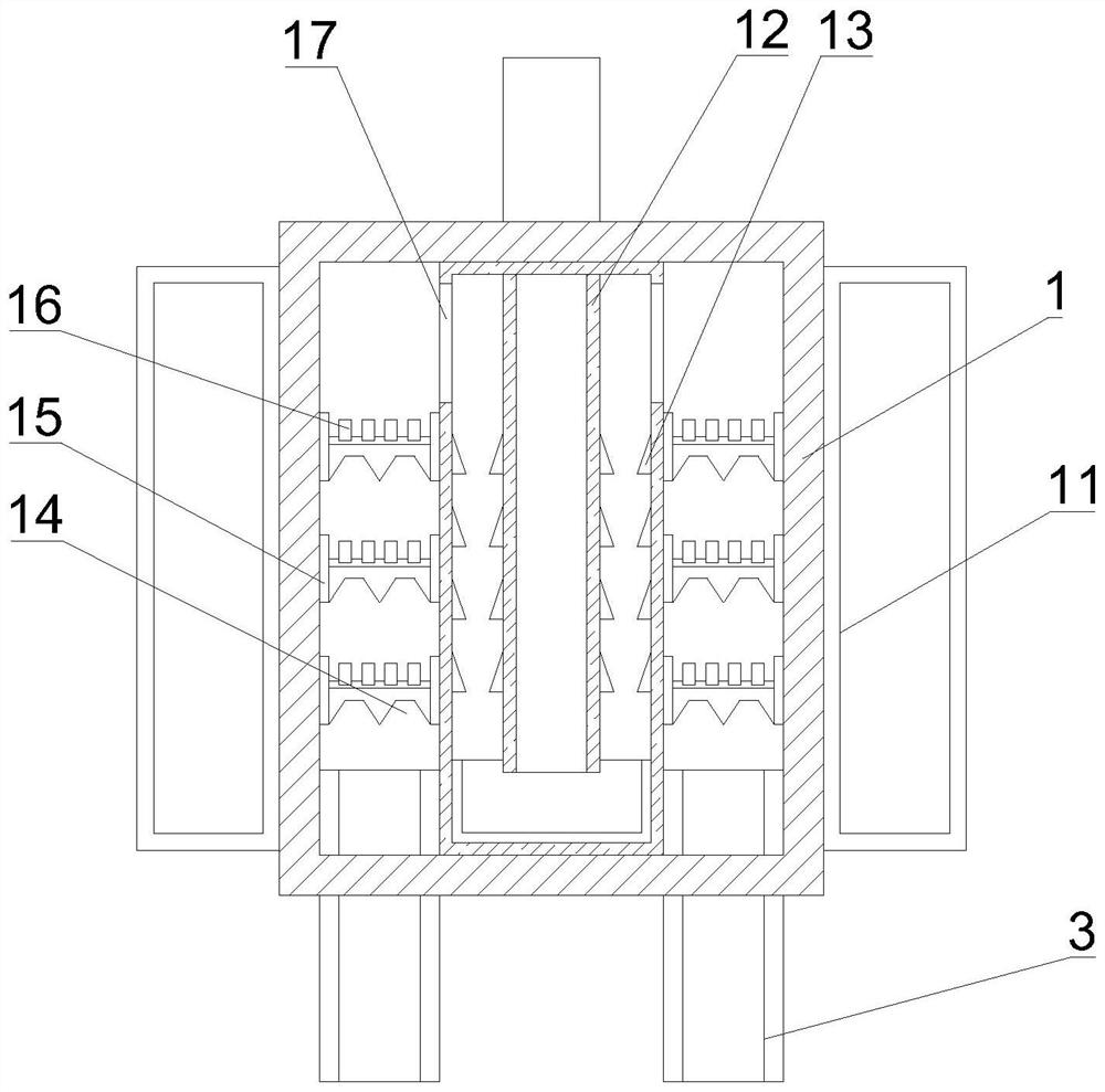
[0041] like Figure 1-7As shown, on the basis of Embodiment 1, the present invention provides a technical solution: preferably, conductive heaters 11 are detachably installed on the outer surfaces of both sides of the water suction pump 1, and the upper and lower inner surfaces of the water suction pump 1 can be The circulating water inlet pipe 12 is detachably connected, and the inner surface of both sides of the conductive heater 11 is fixedly connected with a triangular limit acceleration block 13, and the water suction pump 1 and the inner surface of the circulating water inlet pipe 12 are detachably connected with fixed Block 15, one side outer surface of fixed block 15 is detachably equipped with gathering water deceleration groove 14, and the top outer surface of gathering water decelerating groove 14 is provided with atomization heating pipeline 16, and the two sides of circulating water inlet pipeline 12 Side air inlets 17 are arranged on the outer surface of the side...
Embodiment 3
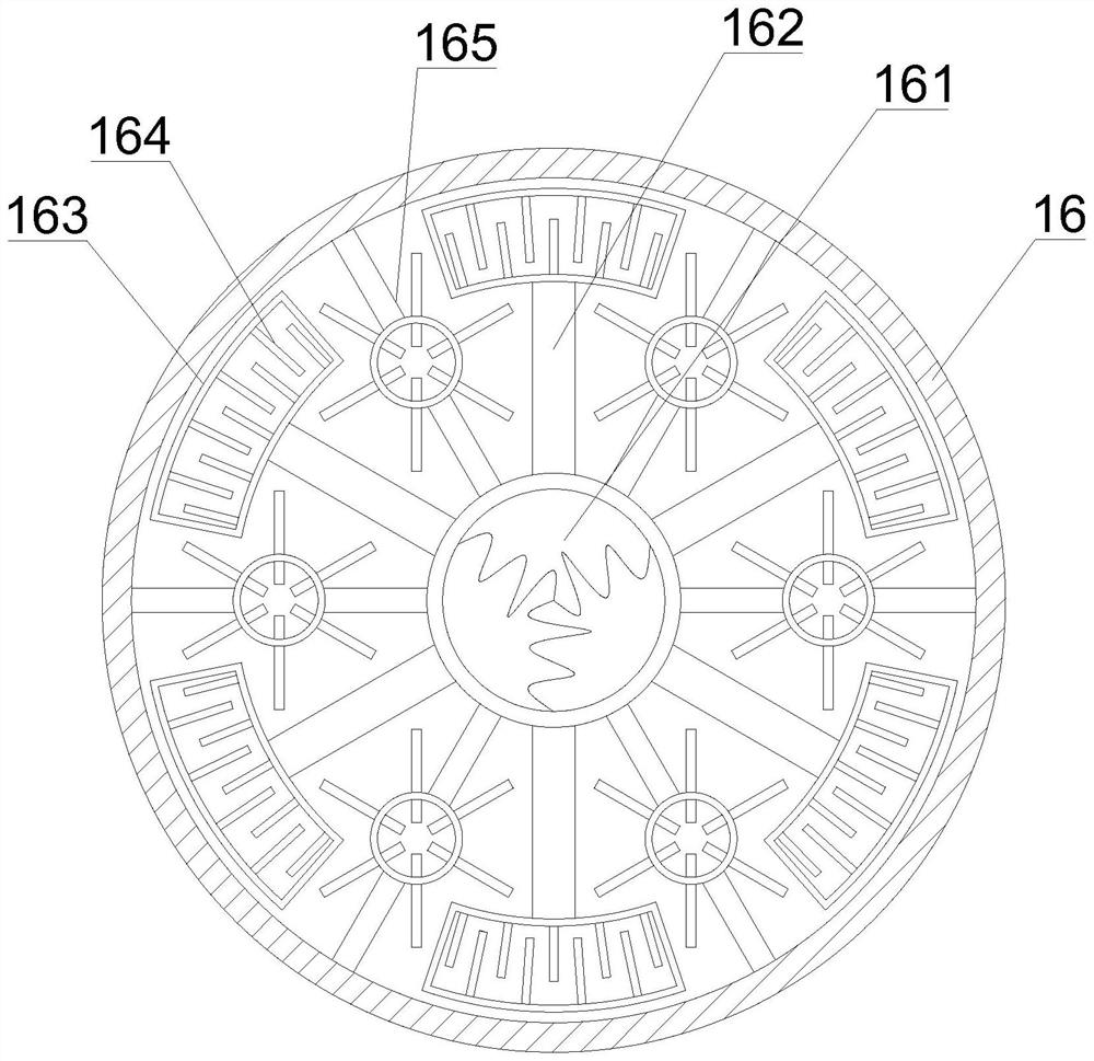
[0044] like Figure 1-7 Shown, on the basis of embodiment 1, the present invention provides a kind of technical scheme: preferably, on the inner surface of both sides of water gathering and speed-reducing groove 14, one-way water guide block 141 is detachably connected, and water-collecting and speed-reducing groove The both sides outer surface of 14 is detachably connected with air intake pipe one 142, and one end of air intake pipe one 142 extends to the inner surface of the water-accumulating speed-reducing groove 14 and is positioned at the inside of one-way water guide block 141, and air intake pipe one An atomizing gas block 143 is fixedly connected to the outer surface of 142, and a U-shaped casing 1431 is detachably connected to the top outer surface of the atomizing gas block 143, and water holes are arranged on the outer surfaces of both sides of the U-shaped casing 1431 1432, the inner surface of the bottom of the U-shaped casing 1431 is provided with an air intake ...
PUM
 Abstract
Description
Claims
Application Information
 - R&D
- Intellectual Property
- Life Sciences
- Materials
- Tech Scout
- Unparalleled Data Quality
- Higher Quality Content
- 60% Fewer Hallucinations
Browse by: Latest US Patents, China's latest patents, Technical Efficacy Thesaurus, Application Domain, Technology Topic, Popular Technical Reports.
© 2025 PatSnap. All rights reserved.Legal|Privacy policy|Modern Slavery Act Transparency Statement|Sitemap|About US| Contact US: help@patsnap.com