Eureka AIR delivers breakthrough ideas for toughest innovation challenges, trusted by R&D personnel around the world.

Positioning equipment for high-precision shaft part detection and use method of positioning equipment

A technology for shaft parts and positioning equipment, which is applied in the direction of measuring devices, workpiece clamping devices, instruments, etc., can solve problems such as detection distortion, processing error, and detection accuracy reduction, and achieve high positioning accuracy, long service life, and eliminate swinging Effect

Pending Publication Date: 2022-03-25
成都华川电装有限责任公司
View PDF4 Cites 0 Cited by
  • Summary
  • Abstract
  • Description
  • Claims
  • Application Information

AI Technical Summary

Problems solved by technology

Since the detection equipment adopts the structure in which one end of the movable support mechanism cooperates with the first mating surface (V-shaped surface) of the tank body and the other end is equipped with a clamping mechanism, when the movable support mechanism cooperates with the first mating surface (V-shaped surface) for positioning, it will There is a certain processing error, which will inevitably lead to a certain swing of the clamping mechanism at the other end, which will be amplified by the movable support mechanism, and the position of the clamping mechanism at the other end will change greatly, resulting in a decrease in detection accuracy or detect distortion

Method used


Image

  • Positioning equipment for high-precision shaft part detection and use method of positioning equipment
  • Positioning equipment for high-precision shaft part detection and use method of positioning equipment
  • Positioning equipment for high-precision shaft part detection and use method of positioning equipment

Examples


Embodiment Construction

[0038] The present invention will be further described below in conjunction with the accompanying drawings and embodiments.

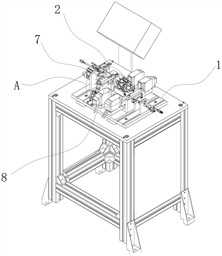
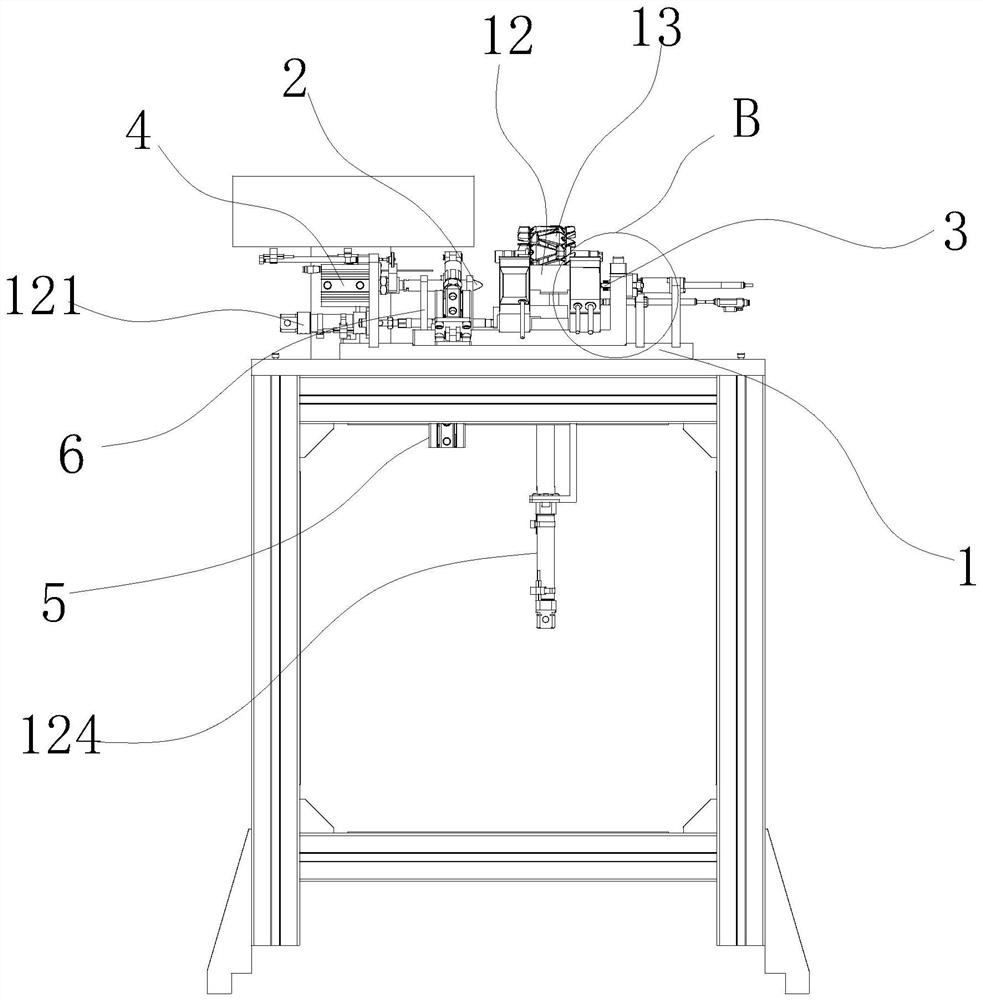
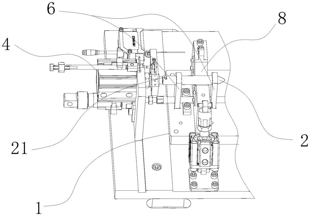
[0039] like Figure 1 to Figure 5 As shown, a positioning device for high-precision shaft parts detection of the present invention includes a base 1 and a fixed center 3 and a movable center 2 installed on the base 1 for clamping both ends of the shaft part. The fixed center 3 and the base 1 fixed connection. The positioning device also includes a first linear driver 4 , a lifting mechanism 5 , a pressing mechanism 7 and a first V-shaped positioning block 8 . The movable center 2 is mounted on the base 1 through a bracket 6 , and the movable center 2 and the bracket 6 are slidably connected along the axial direction of the fixed center 3 . The first V-shaped positioning block 8 is arranged under the movable top 2 and fixedly connected with the base 1 , and the V-shaped groove of the first V-shaped positioning block 8 cooperates with the movable top 2 ...


PUM


Abstract

The invention provides positioning equipment for detecting high-precision shaft parts with high repeated detection positioning precision and a use method of the positioning equipment, and relates to the technical field of auxiliary equipment for detecting the shaft parts. Positioning equipment for high-precision shaft part detection comprises a base, a fixed center and a movable center, and further comprises a first linear driver, a lifting mechanism, a pressing mechanism and a first V-shaped positioning block, the movable center is installed on the base through a support, and the movable center and the support are connected in a sliding mode in the axis direction of the fixed center. The first V-shaped positioning block is arranged below the movable center and fixedly connected with the base, and a V-shaped groove of the first V-shaped positioning block is matched with the movable center; the support is vertically connected with the base in a sliding mode. The lifting mechanism is connected with the support, and the first linear driver is connected with the live center. The device is long in service life, and is suitable for all-number detection of shaft products on an assembly line.

Description

technical field [0001] The invention relates to the technical field of auxiliary equipment for detection of shaft parts, in particular to a high-precision positioning device for detection of shaft parts and a method for using the same. Background technique [0002] During the processing of shaft parts, it is necessary to test the shaft diameter and the distance between the pillow blocks to ensure that the products meet the requirements. The detection accuracy of high-precision shaft products is required to be at the um or sub-um level, and its detection accuracy is mainly affected by two factors: the detection accuracy of the detection equipment and the repeat positioning accuracy of the positioning equipment used for part detection. At present, the detection equipment of shaft parts mostly uses similar scales or light curtain probes, and its detection accuracy is high enough to meet the requirements of use. [0003] For the positioning equipment for shaft parts detection, ...

Claims


Application Information

Patent Timeline
Patent Type & Authority Applications(China)
IPC IPC(8): G01B21/00B25B11/00
CPCG01B21/00B25B11/00
Inventor 陈海军廖珠君陈鹏宇赵耀
Owner 成都华川电装有限责任公司
Why Eureka
Eureka Blog
Learn More