Surface-mounted LED for outdoor display screen
An outdoor display screen, surface mount technology, applied in the direction of identification devices, instruments, etc., can solve the problems of inconvenient disassembly, inability to adjust the position of LED lights, and inability to change the light intensity of the light source, etc., to achieve the effect of easy adjustment
- Summary
- Abstract
- Description
- Claims
- Application Information
AI Technical Summary
Problems solved by technology
Method used
Image
Examples
Embodiment 1
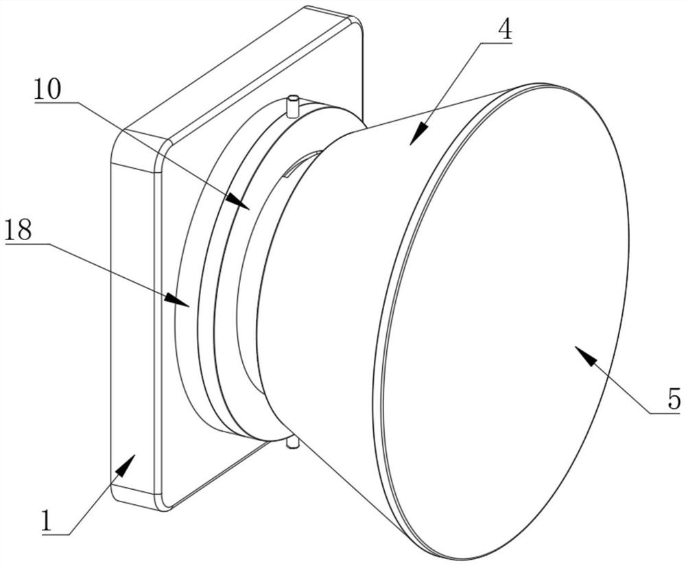
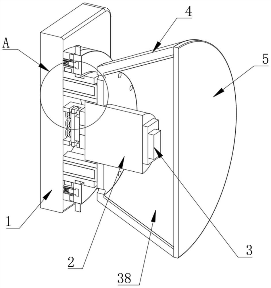
[0034] Embodiment one, by Figure 1 to Figure 9 Given, the present invention includes a mounting base 1 and a lamp body 2, the lamp body 2 is arranged on one side of the mounting base 1, an LED lamp 3 is provided at one end of the lamp body 2, and a lampshade 4 is provided on one side of the mounting base 1 , the lamp body 2 runs through the inner wall of one side of the lampshade 4, a reflector 38 is provided on the inner wall of the lampshade 4, a lens 5 is fixedly connected to one side of the lampshade 4, and an adjustable disassembly assembly is provided between the mounting seat 1 and the lampshade 4 to connect ;
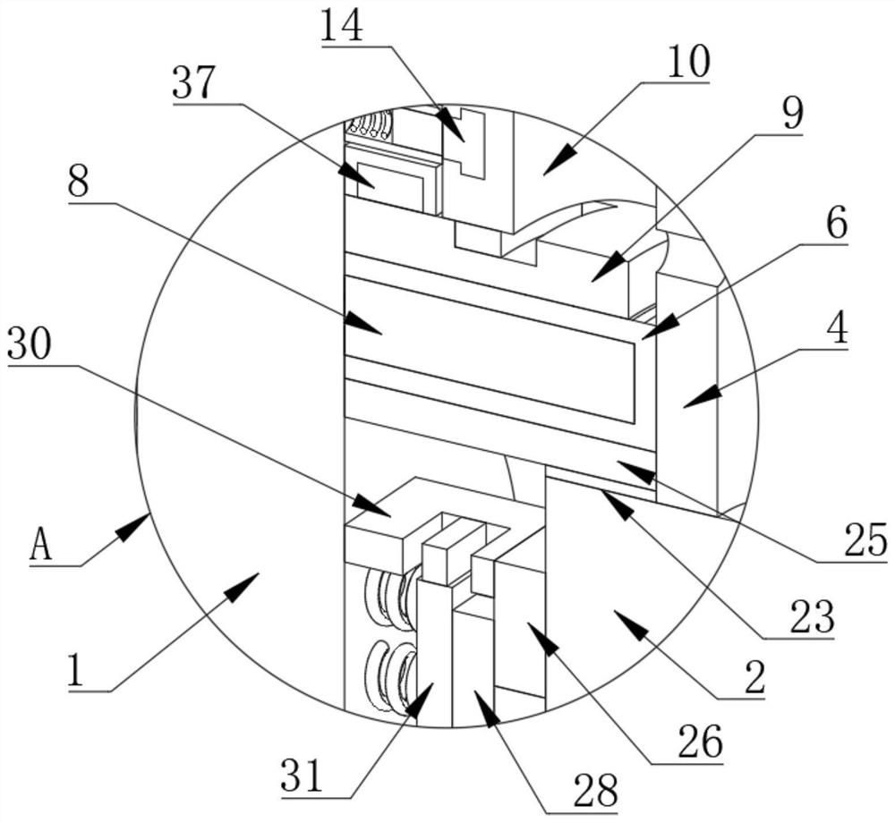
[0035]The adjustable disassembly assembly includes a first threaded tube 6 arranged on one side of the lampshade 4, one side of the first threaded tube 6 is fixedly connected to the lampshade 4, and the first threaded tube 6 is sleeved outside the lamp body 2, and the first threaded tube 6 One side of the tube 6 is provided with a plurality of positioning groo...
Embodiment 2
[0036] Embodiment two, on the basis of embodiment one, by figure 2 and Image 6 Given, the clamping unit includes a fixed ring 18 arranged on one side of the rotating ring 10, one side of the fixed ring 18 is fixedly connected with one side of the mounting seat 1, and one side of the fixed ring 18 is provided with a plurality of slots 19 for inserting Slot 19 is provided with post 20, one end of post 20 is fixedly connected to one side of rotating ring 10, several slots 19 are evenly distributed on one side of fixed ring 18, and positioning posts 8 are evenly distributed on On one side of the seat 1, the positioning column 8 is located in the positioning groove 7, the slider 12 is located in the first chute 11, and the sliding plate 25 is located in the second chute 24;
[0037] Before the rotating ring 10 is driven to rotate, the rotating ring 10 is driven to move away from the fixed ring 18, so that the post 20 is separated from the slot 19, and the position limit of the r...
Embodiment 3
[0038] Embodiment three, on the basis of embodiment two, by figure 2 , image 3 , Image 6 and Figure 8 Given, the elastic rotating assembly includes a first annular groove 13 opened on one side of the rotating ring 10, a supporting ring 14 is arranged in the first annular groove 13, and a plurality of first connecting columns 15 are fixedly connected to one side of the supporting ring 14 One end of the first connecting column 15 is connected to the placement seat 1 through a stretching unit, the cross-section of the support ring 14 and the first annular groove 13 are both T-shaped structures, and the stretching unit includes a One side of the fixed sleeve 16, one end of the fixed sleeve 16 is fixedly connected with one side of the mounting seat 1, one end of the first connecting column 15 is located in the fixed sleeve 16, and the fixed sleeve 16 is provided with a tension spring 17, and the tension spring 17 The two ends of each are fixedly connected with the first conn...
PUM
 Abstract
Description
Claims
Application Information
 - R&D
- Intellectual Property
- Life Sciences
- Materials
- Tech Scout
- Unparalleled Data Quality
- Higher Quality Content
- 60% Fewer Hallucinations
Browse by: Latest US Patents, China's latest patents, Technical Efficacy Thesaurus, Application Domain, Technology Topic, Popular Technical Reports.
© 2025 PatSnap. All rights reserved.Legal|Privacy policy|Modern Slavery Act Transparency Statement|Sitemap|About US| Contact US: help@patsnap.com


