Cooling device suitable for semiconductor laser

A technology for cooling devices and lasers, which is applied in the direction of semiconductor lasers, lasers, laser components, etc., can solve the problems that the cooling device cannot give warnings to the staff, affect the service life of semiconductor lasers, and reduce the heat dissipation effect of electronic components. The overall cost is high, the sensor is easily damaged, and the effect of avoiding economic loss

Pending Publication Date: 2022-03-25
临沂安信电气有限公司
View PDF0 Cites 0 Cited by
  • Summary
  • Abstract
  • Description
  • Claims
  • Application Information

AI Technical Summary

Problems solved by technology

[0003] In order to improve the cooling effect, some semiconductor lasers usually use water-cooled cooling devices. However, during the use of current water-cooled cooling devices, due to the continuous loss of cooling liquid, it is necessary to replenish the cooling liquid in time. However, when the cooling liquid loss is serious (for example, after more than half of the cooling liquid is lost), because the current cooling device cannot give warnings to the staff in time, when the cooling liquid continues to be lost, it will reduce the heat dissipation effect on the electronic components inside the upper shell of the semiconductor laser, or even lose The cooling effect seriously affects the service life of the semiconductor laser, and although some water-cooled cooling devices are equipped with a liquid level detection conduction alarm system, the detection of the liquid level needs to be realized by sensors, which is not only expensive, but also easy damaged

Method used


Image

  • Cooling device suitable for semiconductor laser
  • Cooling device suitable for semiconductor laser
  • Cooling device suitable for semiconductor laser

Examples


Embodiment

[0035] Example: Please refer to Figure 1 to Figure 9 :

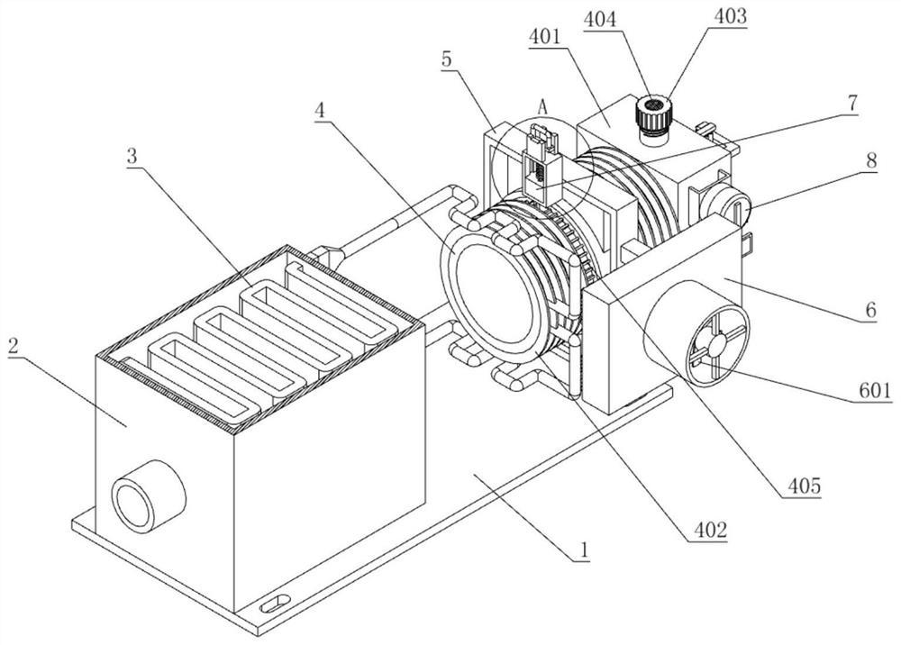
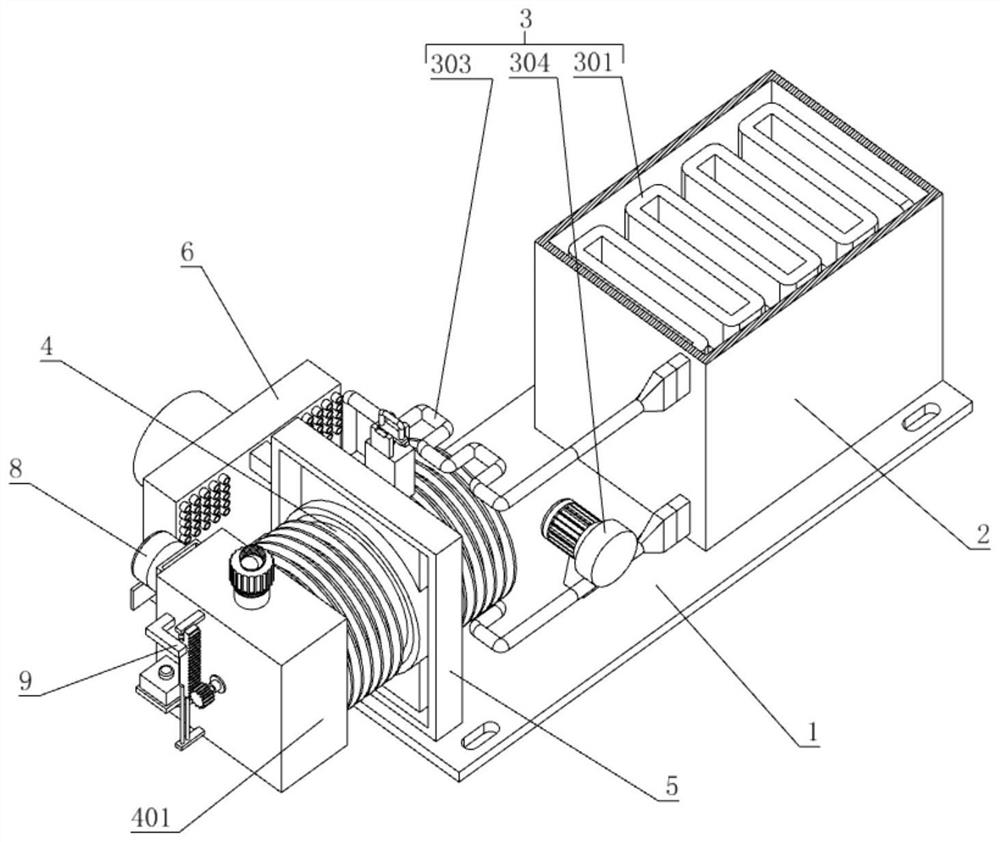
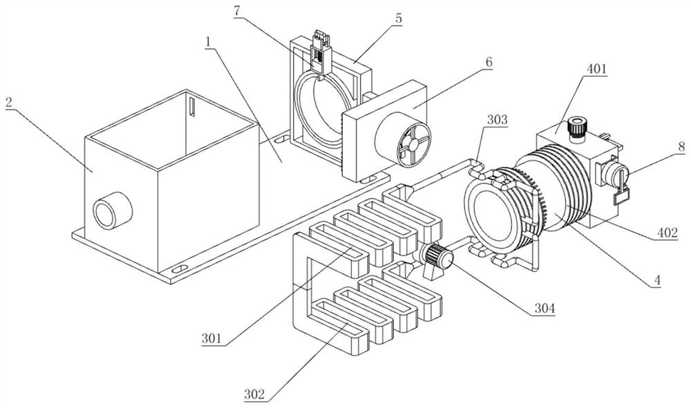
[0036] The present invention proposes a cooling device suitable for semiconductor lasers, comprising: an installation base plate 1; a laser housing 2 is installed on the front side of the upper end of the installation base plate 1, and a support frame 5 is fixed on the rear side of the upper end surface of the installation base plate 1, for The heat part 3 is supported, and the heat absorbing part 3 is installed inside the laser shell 2 for absorbing the heat inside the laser shell 2. The heat absorbing part 3 includes an upper heat absorbing pipe 301, a lower heat absorbing pipe 302, and an infusion hose 303 and circulation pump 304, the upper heat-absorbing pipe 301 and the lower heat-absorbing pipe 302 are respectively installed on the upper and lower sides of the laser housing 2, and the distance between the upper heat-absorbing pipe 301 and the lower heat-absorbing pipe 302 accounts for 1 / 2 of the inner height of t...


PUM


Abstract

The invention provides a cooling device suitable for a semiconductor laser, and relates to the technical field of cooling devices. A laser shell is installed on the front side of the upper end face of the installation bottom plate, a supporting frame is fixed to the rear side of the upper end face of the installation bottom plate, and a heat absorption part is installed in the laser shell. A bearing is installed in the supporting frame, and the supporting frame is rotationally connected with a cooling part through the bearing. The water-cooled cooling device is provided with the buoyancy monitoring part and the small acousto-optic warning indicator, can automatically give an alarm when the cooling liquid is too little, is more reliable in operation through the arrangement of the buoyancy monitoring part, is low in manufacturing cost, is not liable to be damaged, and solves the problem that an existing water-cooled cooling device is not easy to damage when the cooling liquid is seriously lost. The water-cooled cooling device solves the problems that the existing water-cooled cooling devices cannot timely warn workers, and although some existing water-cooled cooling devices are provided with liquid level detection conduction alarm systems, the manufacturing cost is high, and the water-cooled cooling devices are easy to damage.

Description

technical field [0001] The invention relates to the technical field of cooling devices, in particular to a cooling device suitable for semiconductor lasers. Background technique [0002] Semiconductor lasers, also known as laser diodes, are lasers that use semiconductor materials as working substances. During the operation of the laser, a certain amount of heat will be emitted. If it is not cooled in time, it will affect the laser emission effect and service life of the laser. In this case, it must be cooled by a cooling device. [0003] In order to improve the cooling effect, some semiconductor lasers usually use water-cooled cooling devices. However, during the use of current water-cooled cooling devices, due to the continuous loss of cooling liquid, it is necessary to replenish the cooling liquid in time. However, when the cooling liquid loss is serious (for example, after more than half of the cooling liquid is lost), because the current cooling device cannot give warni...

Claims


Application Information

Patent Timeline
IPC IPC(8): H01S5/024H01S5/02315
CPCH01S5/02423H01S5/02315
Inventor 诸葛欣欣
Owner 临沂安信电气有限公司
Why Eureka
Try Eureka