Motor shaft straightening mechanism for motor shaft preparation and use method

A technology for motor shafts and motors, applied in mechanical equipment, safety equipment, manufacturing tools, etc., can solve the problems of workers being easily damaged, lack of buffer, and long time, so as to improve the efficiency of straightening and processing, prevent injuries, The effect of improving the processing quality

Pending Publication Date: 2022-03-29
DALIAN DEMAISHI PRECISION TECH CO LTD
View PDF0 Cites 0 Cited by
  • Summary
  • Abstract
  • Description
  • Claims
  • Application Information

AI Technical Summary

Problems solved by technology

[0003] In the process of motor shaft processing and preparation, it is necessary to carry out motor shaft detection and straightening processing to ensure that the motor shaft is not bent, so as to ensure the effective use of the motor shaft. The traditional method of motor shaft detection and straightening is mostly manual. The first motor shaft is placed in the straightening machine for detection and straightening processing. When this method is used to detect and straighten multiple motor shafts, it takes a long time, which greatly reduces the straightening processing efficiency of the motor shaft, and the motor shaft The processing space is in the open state, and the staff are easily damaged. Secondly, the structure of the existing straightening machine is relatively simple. When the motor shaft is tested and straightened, the stability is poor and there is a lack of a certain buffer, which affects the The effect of motor shaft straightening processing, for this reason, we propose a motor shaft straightening mechanism for motor shaft preparation and its use method to solve the above problems

Method used


Image

  • Motor shaft straightening mechanism for motor shaft preparation and use method
  • Motor shaft straightening mechanism for motor shaft preparation and use method
  • Motor shaft straightening mechanism for motor shaft preparation and use method

Examples


Embodiment

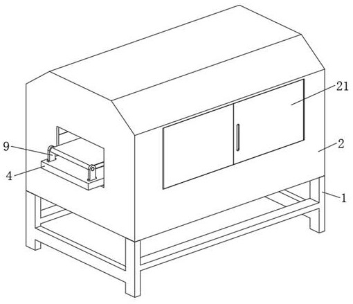
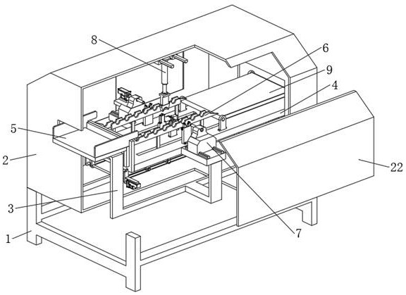
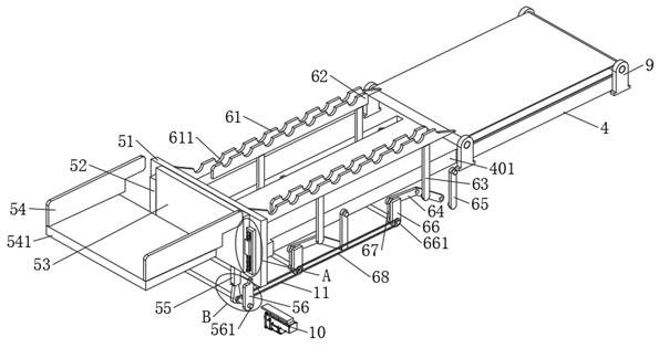
[0044] Example: such as Figure 1-Figure 9 As shown, the present invention provides a motor shaft straightening mechanism for motor shaft preparation, including an underframe 1, a protective frame 2 is fixedly installed on the top of the underframe 1, and a support frame 3 is fixedly installed on the inner and lower walls of the protective frame 2, A bottom plate 4 is fixedly installed on the top of the support frame 3, a feeding assembly 5 is fixedly installed on one side of the bottom plate 4, a material guide assembly 6 used in conjunction with the feeding assembly 5 is provided on the bottom plate 4, and a detection assembly is provided in the middle of the bottom plate 4 7. A straightening assembly 8 corresponding to the detection assembly 7 is fixedly installed on the inner upper wall of the protective frame 2, and a belt conveyor 9 is fixedly installed on the side of the top of the bottom plate 4 away from the feeding assembly 5.

[0045] One side hinge of protective fr...


PUM


Abstract

The invention discloses a motor shaft straightening mechanism for motor shaft preparation and a use method, and particularly relates to the technical field of motor shaft preparation, the motor shaft straightening mechanism comprises a bottom frame, a protection frame is fixedly mounted at the top end of the bottom frame, a supporting frame is fixedly mounted on the inner lower wall of the protection frame, and a bottom plate is fixedly mounted at the top end of the supporting frame; a feeding assembly is fixedly installed on one side of the bottom plate, a material guiding assembly used in cooperation with the feeding assembly is arranged on the bottom plate, a detection assembly is arranged in the middle of the bottom plate, and a straightening assembly corresponding to the detection assembly is fixedly installed on the inner upper wall of the protection frame. According to the automatic straightening device for the motor shafts, the feeding assembly is arranged and used in cooperation with the material guiding assembly, automatic indirect feeding of the multiple motor shafts is achieved, automatic indirect material guiding of the multiple motor shafts is synchronously achieved, and then the subsequent straightening machining efficiency of the motor shafts is improved.

Description

technical field [0001] The invention relates to the technical field of motor shaft preparation, in particular to a motor shaft straightening mechanism for motor shaft preparation and a use method. Background technique [0002] The motor shaft is an important part of the motor. It serves as the link of electromechanical energy conversion between the motor and the equipment, supports the rotating parts, transmits torque and determines the relative position of the rotating parts to the stator. Therefore, the motor shaft must have reliable strength and rigidity to ensure the realization of preset design functions; [0003] In the process of motor shaft processing and preparation, it is necessary to carry out motor shaft detection and straightening processing to ensure that the motor shaft is not bent, so as to ensure the effective use of the motor shaft. The traditional method of motor shaft detection and straightening is mostly manual. The first motor shaft is placed in the st...

Claims


Application Information

Patent Timeline
Patent Type & Authority Applications(China)
IPC IPC(8): B21D3/16B21D43/00B21D43/02B21D55/00B21C51/00F16F15/067
CPCB21D3/16B21D43/003B21D43/02B21D55/00B21C51/00F16F15/067
Inventor 何建平
Owner DALIAN DEMAISHI PRECISION TECH CO LTD
Why Eureka
Try Eureka