Eureka AIR delivers breakthrough ideas for toughest innovation challenges, trusted by R&D personnel around the world.

Quenching mechanism for machining slewing bearing

A technology of slewing bearings and rotating rods, applied in quenching devices, manufacturing tools, heat treatment equipment, etc., can solve the problems of low quenching processing efficiency, inability to rotate slewing bearings, inconvenient quenching processing, etc., and achieve the goal of improving convenience and efficiency Effect

Pending Publication Date: 2022-03-29
徐州健川机械制造有限公司
View PDF0 Cites 2 Cited by
  • Summary
  • Abstract
  • Description
  • Claims
  • Application Information

AI Technical Summary

Problems solved by technology

[0003] 1. In the existing technology, when the slewing bearing is quenched, most of the slewing bearings to be quenched are fixed by bolts, which makes it inconvenient to fix the slewing bearing;
[0004] 2. Most of the existing technologies cannot realize the automatic feeding of the slewing bearing when quenching the slewing bearing, resulting in relatively low quenching processing efficiency of the slewing bearing. At the same time, because the slewing bearing cannot be rotated during the quenching process, thus It makes the quenching process of the inner wall of the slewing bearing more inconvenient. Therefore, we propose a quenching mechanism for processing the slewing bearing to solve the above problems

Method used


Image

  • Quenching mechanism for machining slewing bearing
  • Quenching mechanism for machining slewing bearing
  • Quenching mechanism for machining slewing bearing

Examples


Embodiment

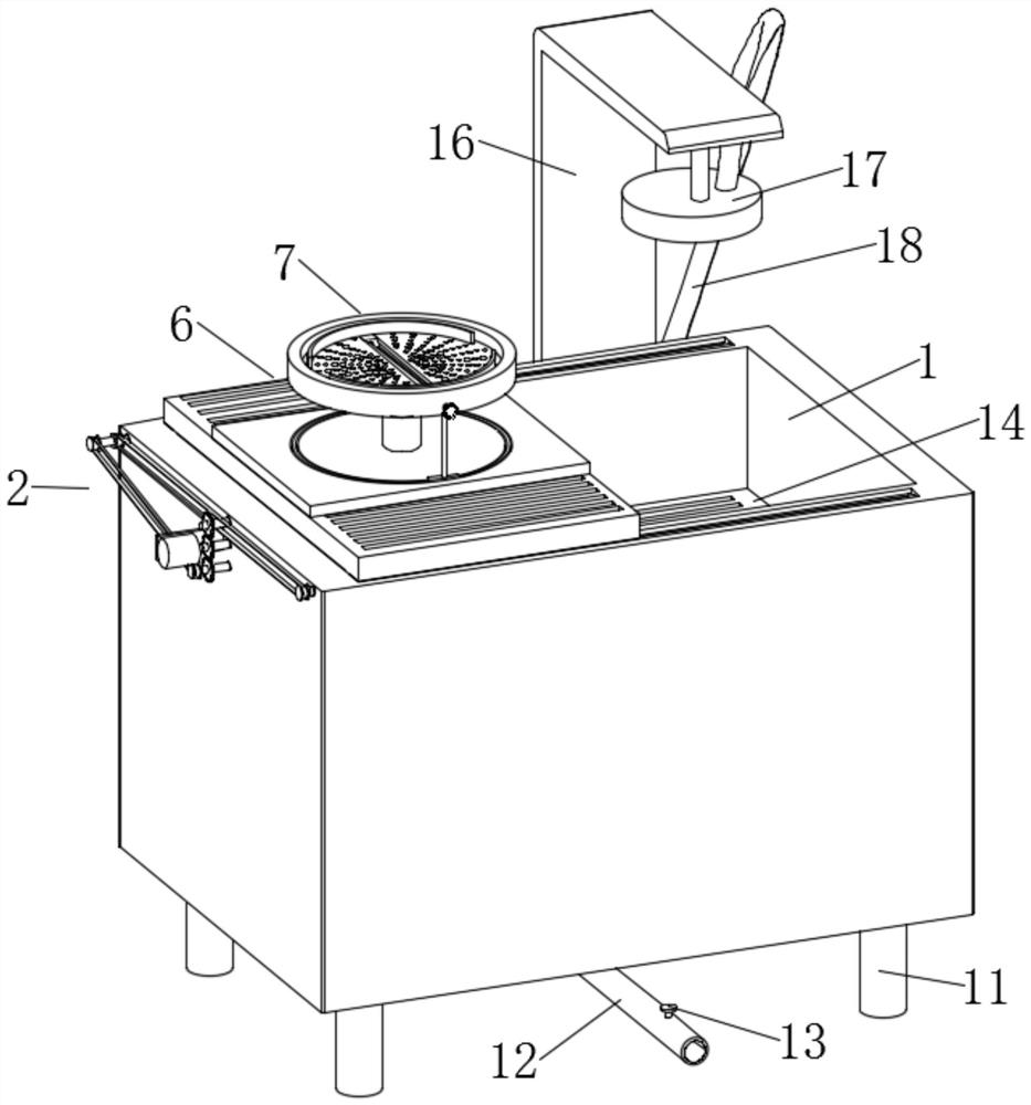
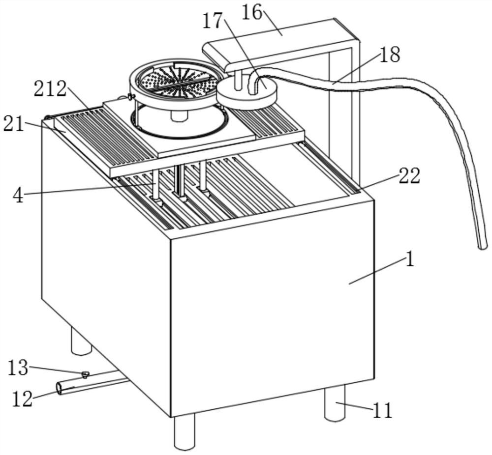
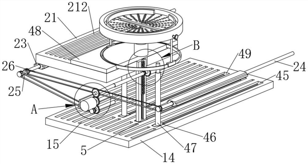
[0031] Example: such as Figure 1-8As shown, the present invention provides a quenching mechanism for processing slewing bearings, including a collection box 1, the bottom of the collection box 1 is fixedly equipped with a sewage pipe 12, the sewage pipe 12 can discharge the processing sewage in the collection box 1, and the collection box A partition 14 is fixedly installed on the inner wall of the collection box 1, and a connecting part 16 is fixedly installed on one side of the collecting box 1. A quenching disc 17 is fixedly installed on the inner wall of the connecting part 16, and the quenching disc 17 is opened by external driving to complete the quenching process of the slewing bearing. The side of the collection box 1 away from the sewage pipe 12 is provided with a feeding mechanism 2, which can conveniently realize the automatic feeding of the slewing bearing, and the surface of the partition 14 is provided with a jacking mechanism 4, which can The slewing bearing to...


PUM


Abstract

The invention discloses a quenching mechanism for machining a slewing bearing, and particularly relates to the field of slewing bearing machining, the quenching mechanism comprises a collecting box, a blow-off pipe is fixedly mounted at the bottom end of the collecting box, a partition plate is fixedly mounted on the inner wall of the collecting box, and a connecting part is fixedly mounted on one side of the collecting box; a quenching disc is fixedly installed on the inner wall of the connecting part, a feeding mechanism is arranged on the face, away from the blow-off pipe, of the collecting box, a jacking mechanism is arranged on the surface of a partition plate, a rotating mechanism is arranged on the surface of the jacking mechanism, and a clamping mechanism is arranged on the surface of the rotating mechanism. The second rotating rod enables the material disc to rotate through the rotating disc, and the slewing bearing rotates synchronously along with the material disc, so that the quenching disc conducts quenching machining on the inner wall of the slewing bearing in the rotating state, quenching machining of the inner wall of the slewing bearing is conveniently completed, and then the convenience of quenching machining of the inner wall of the slewing bearing is effectively improved.

Description

technical field [0001] The invention relates to the technical field of slewing bearing processing, in particular to a quenching mechanism for machining slewing bearings. Background technique [0002] Slewing bearing: The slewing bearing is a new type of mechanical component. It consists of inner and outer rings, rolling elements, etc. The slewing bearing is a large bearing capable of bearing comprehensive loads, and can simultaneously bear large axial and radial loads and overturning moments. The existing technology has the following problems when quenching the slewing bearing: [0003] 1. In the existing technology, when the slewing bearing is quenched, most of the slewing bearings to be quenched are fixed by bolts, which makes it inconvenient to fix the slewing bearing; [0004] 2. Most of the existing technologies cannot realize the automatic feeding of the slewing bearing when quenching the slewing bearing, resulting in relatively low quenching processing efficiency of ...

Claims


Application Information

Patent Timeline
Patent Type & Authority Applications(China)
IPC IPC(8): C21D1/667C21D9/40
CPCC21D1/667C21D9/40C21D9/0018C21D9/0025
Inventor 常军程恒启
Owner 徐州健川机械制造有限公司
Why Eureka
Eureka Blog
Learn More