Compression expansion type energy storage system and energy storage control method

A technology of compression expansion and energy storage system, applied in the direction of combined engines, steam engine devices, machines/engines, etc., can solve the problems of low energy storage density, high cost, poor safety, etc., to reduce equipment costs and occupy a small space , the effect of compact layout

Pending Publication Date: 2022-03-29
INST OF ENGINEERING THERMOPHYSICS - CHINESE ACAD OF SCI
View PDF5 Cites 0 Cited by
  • Summary
  • Abstract
  • Description
  • Claims
  • Application Information

AI Technical Summary

Problems solved by technology

[0004] Therefore, the technical problem to be solved by the present invention is to overcome the defects of high cost, low energy storage density and poor safety in the existing energy storage technology, thereby providing a compression-expansion energy storage system and an energy storage control method

Method used


Image

  • Compression expansion type energy storage system and energy storage control method

Examples


Embodiment 1

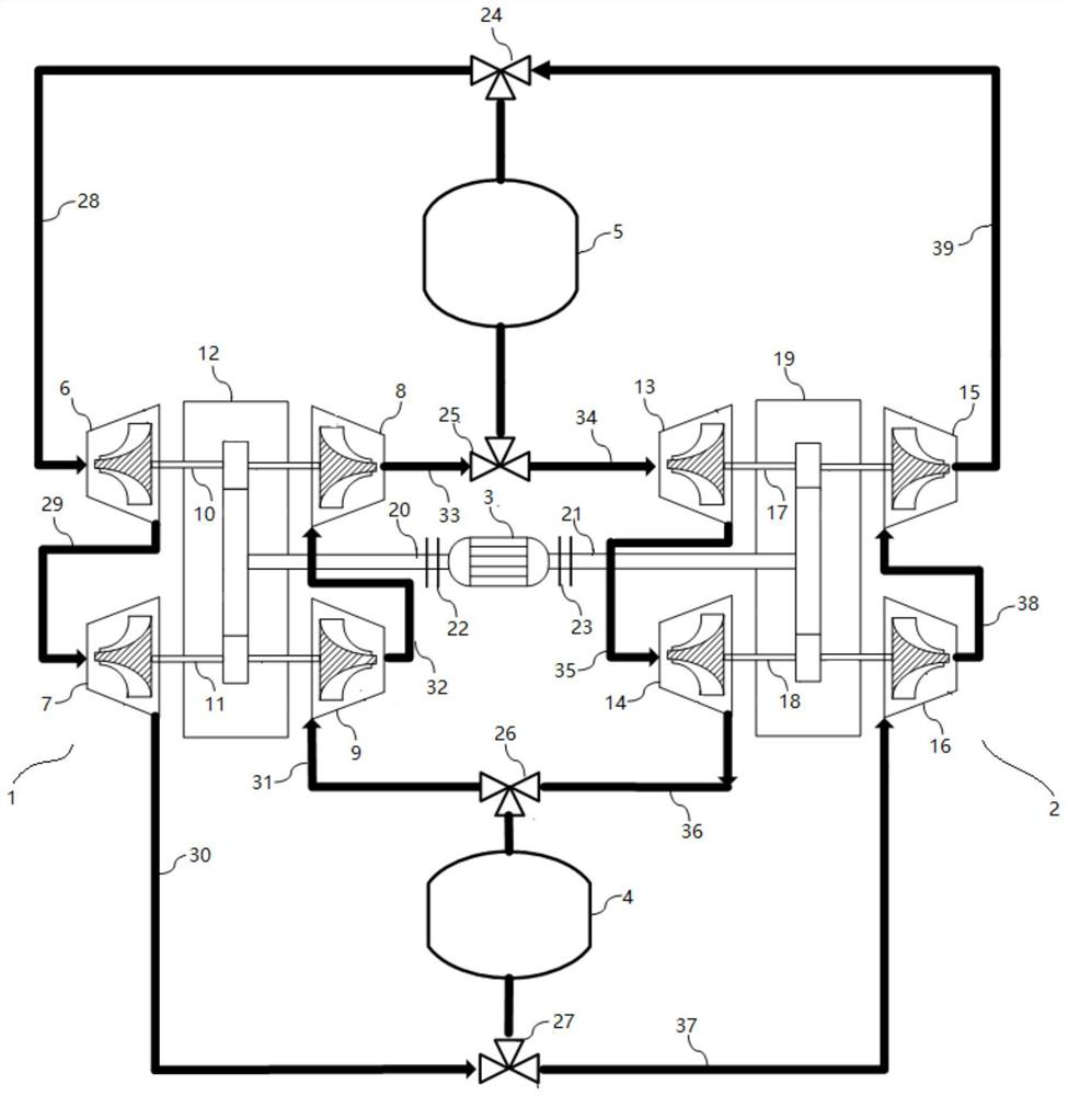
[0036] The compression-expansion energy storage system provided in this embodiment includes: a first energy storage module 1 , a second energy storage module 2 , a main shaft, a motor generator 3 , a heat storage tank 4 and a cold storage tank 5 .

[0037] Such as figure 1 As shown, the first energy storage module 1 has a multi-stage compressor unit and a multi-stage expansion unit, and the number of compressors in the multi-stage compressor unit is consistent with the number of expanders in the multi-stage expansion unit; wherein, the compressor and the expander One-to-one correspondence, a single compressor and a single expander are coaxially connected through a transmission shaft to form a compression expansion unit. In this embodiment, a detailed description is given by taking two-stage compression and two-stage expansion as an example: the multi-stage compressor unit of the first energy storage module 1 has a first low-pressure stage compressor 6 and a first The high-pre...

Embodiment 2

[0047] The energy storage control method of the compression-expansion energy storage system provided in this embodiment includes the following steps:

[0048] When the first energy storage module 1 is working, the first clutch 22 is closed and the second clutch 23 is disconnected at the same time, so that the heat storage tank 4 and the cold storage tank 5 are only connected in series with the first energy storage module 1; that is, to operate the first The control valve 24, the second control valve 25, the third control valve 26 and the fourth control valve 27 make the first air passage 28 communicate with the cold storage tank 5, the third air passage 30 communicate with the heat storage tank 4, and the fourth air passage 30 communicate with the heat storage tank 4. The road 31 communicates with the heat storage tank 4, and the sixth air passage 33 communicates with the cold storage tank 5; at this time, the motor generator 3 is used as a motor to provide power for the first ...


PUM


Abstract

The invention provides a compression expansion type energy storage system and an energy storage control method, and the energy storage system comprises a first energy storage module, a second energy storage module, a third energy storage module and a fourth energy storage module, the compression power consumption of the second energy storage module is smaller than the expansion power generation of the second energy storage module; the first energy storage module and the second energy storage module are coaxially connected through a main shaft, the main shaft is connected with a motor generator, and the motor generator is used for providing mechanical energy needed by the first energy storage module and absorbing mechanical energy of the second energy storage module; the compression loops of the first and second energy storage modules are provided with heat storage tanks, and the expansion loops of the first and second energy storage modules are provided with cold storage tanks. In the energy storage system provided by the invention, when the first energy storage module operates, the first energy storage module is only used as electricity to generate cold and heat and store the cold and heat; and when the second energy storage module operates, the stored cold and heat are utilized to generate electric energy. The first energy storage module and the second energy storage module can be selectively switched according to use requirements; the operation mode of the energy storage system is flexible and adjustable.

Description

technical field [0001] The invention relates to the technical field of heat pump power storage, in particular to a compression-expansion energy storage system and an energy storage control method. Background technique [0002] With the depletion of traditional energy, today's society has higher and higher requirements for the use of renewable energy. How to improve the utilization efficiency and quality of renewable energy has become the focus of global attention. Energy storage technology is considered to be a key technology for the large-scale application of renewable energy. [0003] At present, energy storage technologies include physical energy storage such as pumped storage and compressed air energy storage, and electrochemical energy storage technologies such as lithium batteries, but their large-scale application has problems such as high cost and poor safety. Contents of the invention [0004] Therefore, the technical problem to be solved by the present inventio...

Claims


Application Information

Patent Timeline
Patent Type & Authority Applications(China)
IPC IPC(8): F01D13/00F01K7/02
CPCF01D13/003F01K7/02
Inventor 王亮张涵陈海生林曦鹏李文左志涛
Owner INST OF ENGINEERING THERMOPHYSICS - CHINESE ACAD OF SCI
Why Eureka
Try Eureka