
Three-dimensional space position continuous change combined measurement device and measurement method

A technology of three-dimensional space and measuring devices, applied in measuring devices, measuring instruments, surveying and navigation, etc., can solve the problems of inability to achieve full coverage of three types of parameters, lack of displacement parameters, monitoring blind spots, etc., to improve the level of structural safety assurance , Avoid monitoring blind spots, high reliability effect

Pending Publication Date: 2022-04-05
HUBEI SANJIANG AEROSPACE HONGFENG CONTROL
View PDF9 Cites 0 Cited by
  • Summary
  • Abstract
  • Description
  • Claims
  • Application Information

AI Technical Summary

Problems solved by technology

However, the current monitoring methods for the three-dimensional space position change of the structure are still insufficient, mainly reflected in: first, the coverage capacity is insufficient, and the measured target cannot be continuously covered, and only a single point can be measured; second, the parameters are missing, and the three-dimensional space of the structure The position change is composed of three types of displacement parameters, which are overall translation, overall rotation, and continuous deformation. However, the current technical means only measure one or two parameters one-sidedly, and cannot achieve full coverage of the three types of parameters.
The lack of spatial position leads to monitoring blind spots, and the lack of displacement parameters leads to monitoring risks. Therefore, it is urgent to develop a comprehensive and safe new structural safety monitoring technology to obtain the continuous change of the three-dimensional spatial position of the target structure and increase the level of structural safety assurance.

Method used


Image

  • Three-dimensional space position continuous change combined measurement device and measurement method
  • Three-dimensional space position continuous change combined measurement device and measurement method
  • Three-dimensional space position continuous change combined measurement device and measurement method

Examples


Embodiment Construction

[0029] In order to make the object, technical solution and advantages of the present invention clearer, the present invention will be further described in detail below in conjunction with the accompanying drawings and embodiments. It should be understood that the specific embodiments described here are only used to explain the present invention, not to limit the present invention. In addition, the technical features involved in the various embodiments of the present invention described below can be combined with each other as long as they do not constitute a conflict with each other.

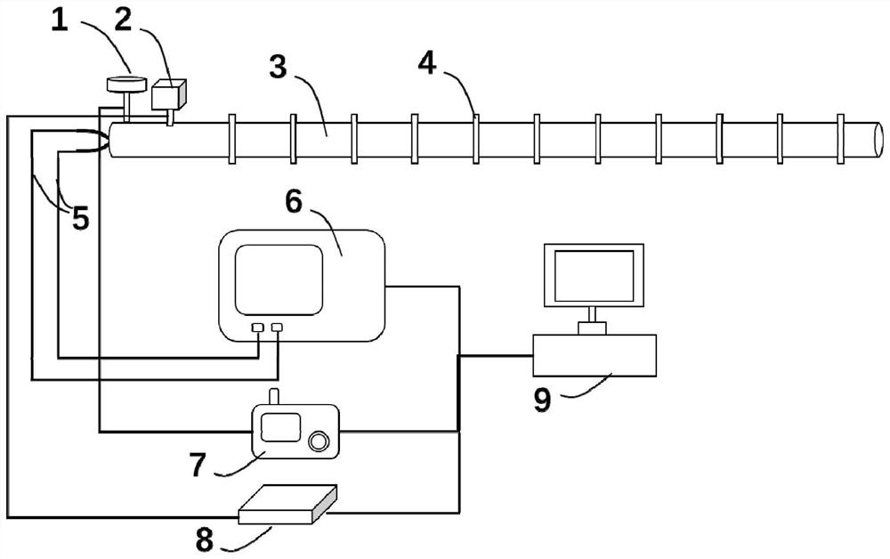
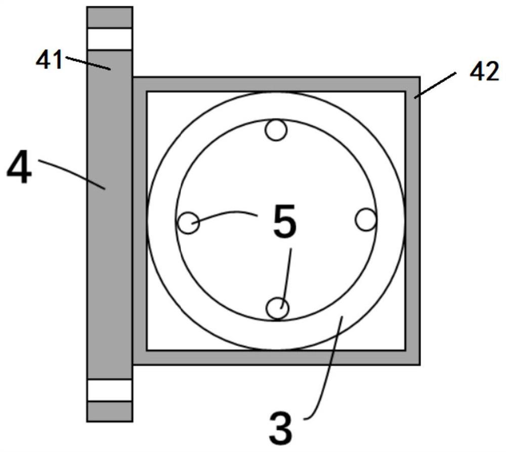
[0030] like figure 1 As shown, a three-dimensional space position continuous change combined measuring device according to an embodiment of the present invention includes: a positioning sensor 1, a three-way inclination sensor 2, a continuous deformation measuring tube 3, a fixed module 4, a strain sensing optical fiber 5 and a data acquisition process module, the continuous deformation measuri...


PUM


Abstract

The invention discloses a three-dimensional space position continuous change combined measurement device and a measurement method. The device comprises a positioning sensor, a three-way tilt angle sensor, a continuous deformation measuring tube, a fixing module, a strain sensing optical fiber and a data collecting and processing module, and the positioning sensor, the three-way tilt angle sensor and the continuous deformation measuring tube are directly or indirectly fixed to a measured target through the fixing module. The strain sensing optical fiber is arranged on the continuous deformation measuring tube, and the data acquisition and processing module is used for receiving data acquired by the positioning sensor, the three-way tilt angle sensor and the continuous deformation measuring tube and calculating and determining a position continuous change value of a measured target in a three-dimensional space. According to the invention, continuous change measurement of the three-dimensional space position of the target can be realized, the full length of the measured target can be covered, three kinds of displacement components of translation, rotation and deformation can be completely acquired, the measurement result information is complete, the monitoring blind area is avoided, and the structure safety monitoring level is improved.

Description

technical field [0001] The invention belongs to the technical field of structural safety monitoring, and more specifically relates to a three-dimensional space position continuous change combination measuring device and a measuring method. Background technique [0002] During the long-term service of long-distance engineering structures such as bridges, pipelines, and tunnels, due to various factors such as material aging, fatigue loading, foundation settlement, support displacement, and eccentric loads, the structure gradually develops complex spatial position changes. Without timely monitoring, there will be serious consequences such as bridge beam falling, pipeline cracking, and tunnel collapse. However, the current monitoring methods for the three-dimensional space position change of the structure are still insufficient, mainly reflected in: first, the coverage capacity is insufficient, and the measured target cannot be continuously covered, and only a single point can b...

Claims


Application Information

Patent Timeline
IPC IPC(8): G01C15/00
CPCY02E30/30
Inventor 葛来徐金龙崔莅杭
Owner HUBEI SANJIANG AEROSPACE HONGFENG CONTROL
Learn More