CT imaging device

A technology of CT imaging and ray source, which is applied in the field of non-destructive testing, can solve the problems of difficult to realize the clamping and high-precision detection of slender rods, the inability to meet the detection requirements of nuclear fuel rods, and the long time-consuming of nuclear fuel rods, etc., so as to improve the overall detection effect , eliminate imaging interference, and reduce measurement time

Pending Publication Date: 2022-04-05
CHINA ELECTRONIC TECH GRP CORP NO 38 RES INST
View PDF11 Cites 2 Cited by
  • Summary
  • Abstract
  • Description
  • Claims
  • Application Information

AI Technical Summary

Problems solved by technology

[0004] However, it cannot meet the detection requirements of nuclear fuel rods. Firstly, it is difficult to realize the clamping and high-precision detection of slender rods by using the vertical rotation method. Secondly, it takes a long time and low efficiency to perform high-precision detection of the entire nuclear fuel rod.

Method used


Image

  • CT imaging device
  • CT imaging device
  • CT imaging device

Examples


Embodiment Construction

[0029] In order to make the purpose, technical solutions and advantages of the embodiments of the present invention clearer, the technical solutions in the embodiments of the present invention will be clearly and completely described below in conjunction with the embodiments of the present invention. Obviously, the described embodiments are part of the present invention Examples, not all examples. Based on the embodiments of the present invention, all other embodiments obtained by persons of ordinary skill in the art without creative efforts fall within the protection scope of the present invention.

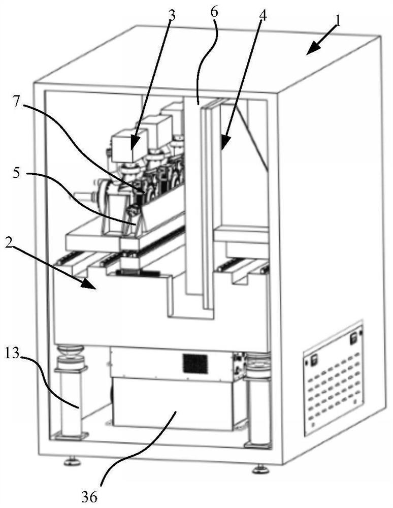
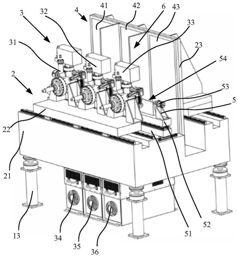
[0030] The object to be tested in this embodiment is an elongated rod as an example. In this embodiment, high thermal stability granite is selected to build the support structure. The thermal melting ratio is far lower than that of conventional materials such as stainless steel. The slow heating rate greatly eliminates Temperature changes ensure the accuracy of CT scanning; secon...


PUM


Abstract

A CT imaging device disclosed by the present invention comprises a shielding cabinet, a multi-axis motion platform, a ray source assembly, a detection assembly, a loading platform and an X-ray shielding plate, the multi-axis motion platform, the ray source assembly, the detection assembly, the loading platform and the X-ray shielding plate are all located in the shielding cabinet, and the multi-axis motion platform comprises a base. The radiation source assembly and the detection assembly are arranged on the base in a sliding mode in the length direction of the to-be-detected piece, the radiation source assembly comprises a plurality of radiation sources, and the detection assembly comprises a plurality of detectors. According to the invention, the object carrying platform is used for rotatably fixing the to-be-detected piece and is matched with the ray source assembly and the detection assembly to synchronously move along the length direction of the to-be-detected piece, so that semi-circumferential or whole-circumferential equal scanning detection of different faults of the to-be-detected piece can be met, and the measurement precision is improved.

Description

technical field [0001] The invention relates to the technical field of non-destructive testing, and more particularly to a CT imaging device. Background technique [0002] The nuclear fuel is encapsulated in a slender cylindrical cladding tube with a length of several meters and a thickness not greater than 10mm. Parameters such as permeation and cladding end seals all directly affect fuel performance. Industrial CT can not only intuitively and clearly display the structural relationship and defect status of the internal details of the object in the form of images under non-destructive conditions, but also realize high-precision non-destructive measurement of the internal and external geometric dimensions of the object. Compared with other detection and measurement methods, industrial CT can not only measure the complex geometric shape parameters of the workpiece, but also detect internal structural defects and measure the geometric shape parameters of the internal structur...

Claims


Application Information

Patent Timeline
Patent Type & Authority Applications(China)
IPC IPC(8): G01N23/046
Inventor 何张强张腊梅李俊英李旺吴后平徐松朱伟林
Owner CHINA ELECTRONIC TECH GRP CORP NO 38 RES INST
Why Eureka
Try Eureka