A reflective star sensor

A star sensor, reflective technology, applied in celestial navigation and other directions, can solve the problems of chromatic aberration of magnification, increase of star point image spot size, limitation of stray light elimination ability, reduction of star sensor sensitivity, etc., to eliminate uncertainty Error, spectral type range expansion, overcoming the effect of low tolerance

Active Publication Date: 2020-09-18
BEIJING INST OF CONTROL ENG
View PDF17 Cites 0 Cited by
  • Summary
  • Abstract
  • Description
  • Claims
  • Application Information

AI Technical Summary

Problems solved by technology

[0005] (1) Chromatic aberration is common in transmissive optical systems, and the low-frequency error of the star sensor caused by the chromatic aberration of magnification is difficult to eliminate, and the low-frequency error is the main error that affects the star sensor to achieve very high precision
[0006] (2) Limited by the ability of chromatic aberration correction and the size of the star point, the working spectrum of the transmission optical system used in the existing transmission star sensor should not be too wide. Too wide a working spectrum will cause a large chromatic aberration of magnification The increase in the size of the star point and image spot cannot meet the design requirements of the star sensor. In addition, the narrowing of the working spectrum leads to a decrease in the sensitivity of the star sensor, the quantum efficiency of the detector cannot be fully utilized, and the spectral range of the star catalog is limited.
[0007] (3) The size and weight of the hood of the existing transmissive star sensor is relatively large, the ability to eliminate stray light is limited to a certain extent, and the means of eliminating stray light inside the lens are limited
[0008] (4) Due to the thermal optical characteristics of the existing transmissive star sensor optical system, it is difficult to eliminate the change of the temperature field, and the means of thermal compensation through the optical-mechanical structure are limited, and the position of the imaging star point will be caused when the temperature field of the working environment changes. Drift, causing the optical axis of the star sensor to drift

Method used


Image

  • A reflective star sensor
  • A reflective star sensor
  • A reflective star sensor

Examples


Embodiment 1

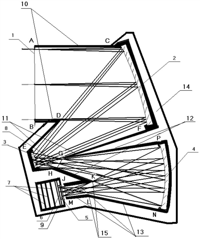
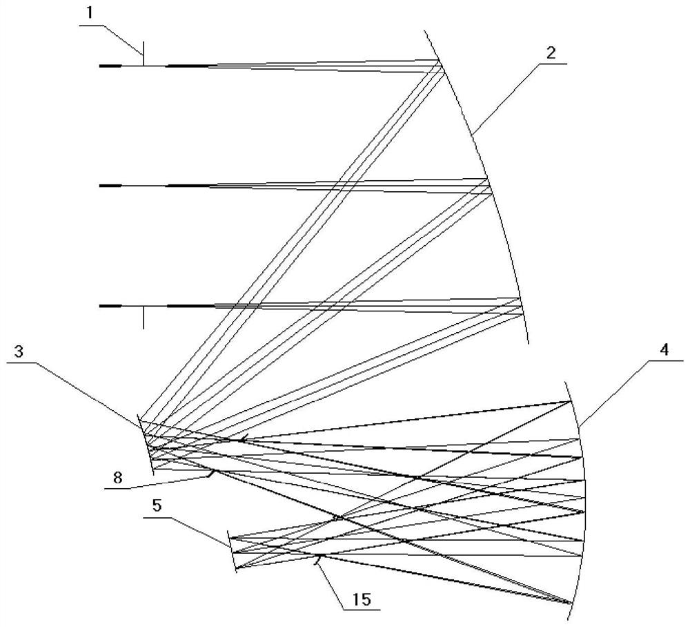
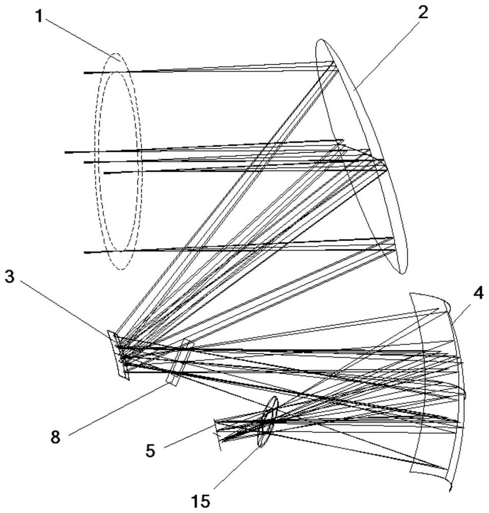
[0041] The scheme of reflective star sensor: consists of aperture diaphragm 1, main mirror 2, secondary mirror 3, third mirror 4, photodetector 5, detector circuit 6, information processor circuit 7, intermediate image diaphragm 8. The information processor 9, the first section of the light shield 10, the second section of the light shield 11, the third section of the light shield 12, the fourth section of the light shield 13, the supporting structure 14, and the Leo diaphragm 15.

[0042] The stellar target light first passes through figure 1 The aperture stop 1 of the lens passes through the first section of the hood 10, enters the main reflector 2, and then passes through the second section of hood 11, reaches the secondary reflector 3, and then passes through the intermediate image stop 8 and the third section of hood in turn 12. Reach the third reflector 4, then pass through the third section of the light shield 12 to the third reflector 4, and then go through the Leo diaphra...


PUM


Abstract

The invention discloses a reflective star sensor. The reflective star sensor comprises an off-axis three-reflection optical system, a light shield, a detector and an information processor. The opticalsystem is an off-axis three-reflector system with an intermediate image diaphragm and a Leo diaphragm. The detector is a solid-state imaging device. The information processor is an embedded system with effects of collecting and storing the photoelectric digital images formed by the detector and calculating the outputting attitude information. The reflective star sensor has a series of advantagessuch as a low frequency error of a star sensor caused by no color difference, an extremely small optical axis heat drift caused by an optical machine material with a near zero thermal expansion coefficient and parasitic light eliminating convenience caused by the intermediate image diaphragm and the Leo diaphragm, and the existing star sensor cannot simultaneously have the above advantages.

Description

Technical field [0001] The invention relates to a reflective star sensor, which can be applied to the field of spacecraft attitude measurement and rotation angular rate measurement. Background technique [0002] At present, star sensors are often used for the attitude measurement of spacecraft. The main principle of this sensor is to use the law that the position of stars is basically immobile relative to inertial space, and obtain star maps by photoelectric imaging of stars in a sky area. After the image is processed and identified, the optical axis of the measurement sensor is pointed in the inertial space, and the three-axis attitude of the spacecraft can be obtained through the conversion between the spacecraft installation coordinate system of the star sensor and the spacecraft attitude coordinate system. [0003] In the prior art, the star sensor hardware includes a hood, an optical system (lens), an electronic system, electrical appliances, and structural interfaces. The el...

Claims


Application Information

Patent Timeline
Patent Type & Authority Patents(China)
IPC IPC(8): G01C21/02
CPCG01C21/02
Inventor 郝云彩
Owner BEIJING INST OF CONTROL ENG
Why Eureka
Try Eureka