Pulse truss sprinkling machine and operation method

A sprinkler and pulse technology, which is applied in the field of agricultural water-saving irrigation, can solve the problems of reducing the operation efficiency of the sprinkler, high sprinkler intensity, and small sprinkler range, and achieves the effects of increasing the spray uniformity, reducing the sprinkler intensity and ensuring the range.

Active Publication Date: 2022-04-08
JIANGSU UNIV
View PDF7 Cites 0 Cited by
  • Summary
  • Abstract
  • Description
  • Claims
  • Application Information

AI Technical Summary

Problems solved by technology

However, the existing truss-type sprinklers are equipped with small sprinkler nozzles and high sprinkler intensity, resulting in the sprinkler irrigation intensity often greater than the soil infiltration capacity, resulting in surface runoff, causing deep seepage and soil erosion, and reducing the operating efficiency of the sprinkler irrigation machine

Method used


Image

  • Pulse truss sprinkling machine and operation method
  • Pulse truss sprinkling machine and operation method
  • Pulse truss sprinkling machine and operation method

Examples


Embodiment 1

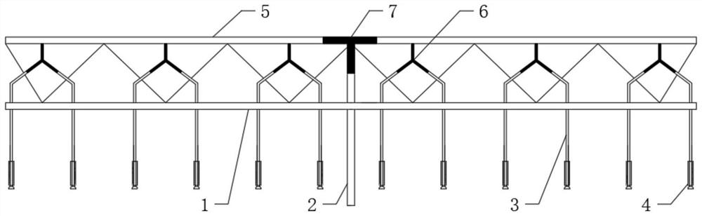
[0036] combined with figure 1 As shown, a pulse truss irrigation machine includes a truss 1, a main pipe 2, a capillary 3, a nozzle 4, a branch pipe 5, a capillary jet pulse tee 6, and a branch jet pulse tee 7; the branch pipe 5 is fixed on the truss 1 , the branch pipe 5 and the main pipe 2 are connected by the branch jet pulse tee 7, the inlet end of the capillary jet pulse tee 6 is vertically connected with the branch pipe 5, the two outlet ends of the capillary jet pulse tee 6 are respectively connected to a capillary 3, and the end of the capillary 3 is connected to the nozzle 4.

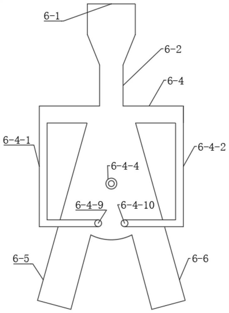
[0037] combined with figure 2 , image 3 As shown, the capillary jet pulse tee 6 and the branch jet pulse tee 7 include a water inlet 6-1, a jet pipe 6-2, a jet space 6-3, a reversing device 6-4, an output pipe 6-5, and an outlet 6 -6; the water inlet 6-1 is connected to a shrink tube, and the shrink tube is connected to the jet tube 6-2; the jet tube 6-2 is connected to the jet space 6-3; ...

Embodiment 2

[0044] combined with Figure 1 to Figure 4 As shown, the basic structural features and implementation method of Embodiment 2 are similar to Embodiment 1, and the difference from Embodiment 1 lies in the structure and reversing method of the jet reversing device 6-4.

[0045] combined with Figure 4 As shown, the jet reversing device 6-4 is a negative pressure reversing device, including a left reversing channel 6-4-1 and a right reversing channel 6-4-2; Holes are opened on the wall, and the left reversing channel 6-4-1 and the right reversing channel 6-4-2 are respectively connected; the water flow enters the jet space 6-3 through the jet tube 6-2 to form a jet, which produces a wall attachment effect; if Attach the wall to the left wall of the jet space 6-3 first, and generate negative pressure in the left reversing channel 6-4-1 by the entrainment of the jet; as the jet continues, the negative pressure will be transmitted to the right reversing channel In 6-4-2, a pressure...

Embodiment 3

[0047] combined with Figure 1 to Figure 5 As shown, the basic structural features and implementation method of Embodiment 3 are similar to Embodiment 1, and the difference from Embodiment 1 lies in the structure and reversing method of the jet reversing device 6-4.

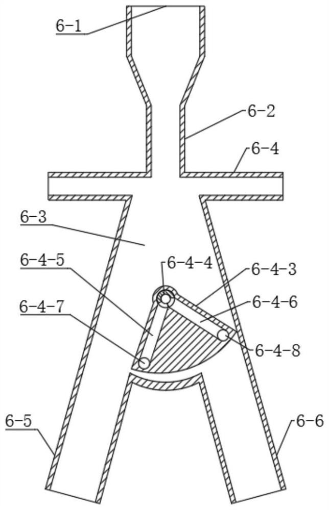
[0048] combined with Figure 5 As shown, the jet reversing device 6-4 is a hydraulic reversing device, including a left reversing channel 6-4-1 and a right reversing channel 6-4-2; A hole is respectively opened on the wall, and a hole is respectively opened on the outer wall surface of the left output pipe 6-5 and the right output pipe 6-6, and the two holes on the same side are connected with the passage to form the left reversing passage 6-4- 1. The right reversing channel 6-4-2; the pressure water flow enters the jet space 6-3 through the jet tube 6-2 to form a jet, and the wall attachment effect is produced under the action of jet entrainment; if the wall is first attached to the jet space 6-3 The left wall...


PUM


Abstract

The invention discloses a pulse truss sprinkling machine and an operation method, and belongs to the technical field of agricultural water-saving irrigation. The pulse truss sprinkling machine comprises a truss, a main pipe, capillary pipes, nozzles, branch pipes, capillary pipe jet flow pulse tee joints and branch pipe jet flow pulse tee joints; wherein the jet pulse tee joint comprises a water inlet, a jet pipe, a jet space, a jet reversing device, an output pipe and an outlet; when the pulse truss sprinkling machine works, pressure water flow enters the water inlet of the jet pulse tee joint, enters the jet space through the jet pipe to form jet flow, is attached to one side wall surface of the jet space and enters the branch pipe or the capillary pipe on the side wall surface; through the reversing effect of the vibrator reversing device, water flow is periodically switched and output at the left outlet and the right outlet, and pulse water flow is generated in the branch pipes and the capillary pipes respectively. Pulse water flows of the branch pipes and the capillary pipes are overlapped and then enter the spray heads, so that the spray heads form a pulse spraying effect, the spray irrigation intensity is reduced, and the spraying uniformity is improved.

Description

technical field [0001] The invention belongs to the technical field of agricultural water-saving irrigation, and relates to a truss type sprinkler irrigation machine, in particular to a pulse truss sprinkler irrigation machine and an operation method. Background technique [0002] The truss type sprinkler irrigation machine has the characteristics of saving water and labor, a high degree of mechanization, a large single-machine control area, and strong adaptability. In recent years, the scope of promotion and application has been expanding year by year. However, the existing truss-type sprinklers are configured with a small nozzle range and a high sprinkler intensity, so that the sprinkler intensity is often greater than the soil infiltration capacity, and surface runoff occurs, causing deep seepage and soil erosion, reducing the operating efficiency of the sprinkler. The invention designs a pulse truss sprinkling irrigation machine, which has the effect of pulse spraying. T...

Claims


Application Information

Patent Timeline
Patent Type & Authority Applications(China)
IPC IPC(8): A01G25/09
CPCY02A40/22
Inventor 王新坤
Owner JIANGSU UNIV
Why Eureka
Try Eureka