
Feeding mechanism

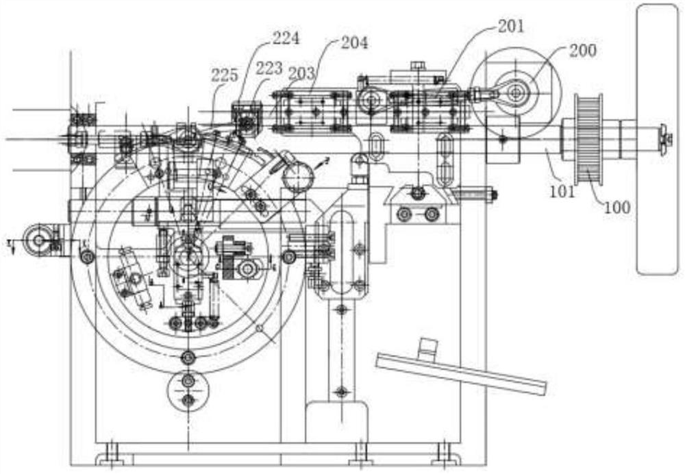
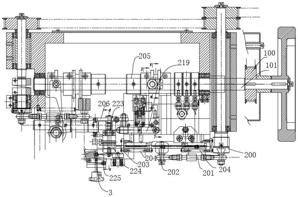
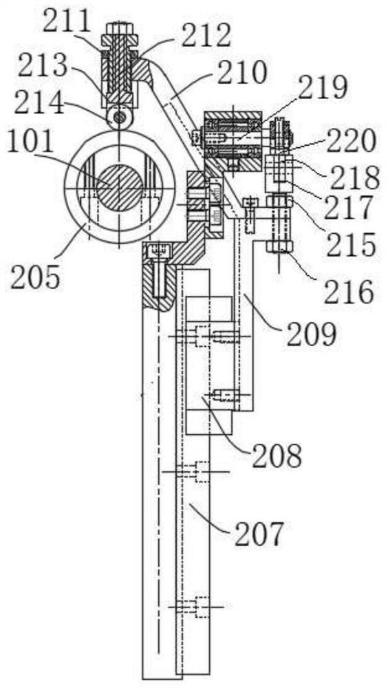
A technology of feeding mechanism and lifting mechanism, which is applied in the direction of auxiliary devices, auxiliary welding equipment, welding/cutting auxiliary equipment, etc., can solve the problems of dislocation of two metal chains and high requirements for pushing precision, so as to improve the effect of chain feeding and meet the mechanical requirements. High-speed feeding, ingenious effect

Pending Publication Date: 2022-04-08
深圳市罗福鑫科技有限公司
View PDF0 Cites 0 Cited by
  • Summary
  • Abstract
  • Description
  • Claims
  • Application Information

AI Technical Summary

Problems solved by technology

In the production process of the double chain, two metal chains need to be placed side by side. When welding, the two metal chains need to be pushed forward to complete the welding of the entire metal chain. However, because the metal chains are relatively small, the precision requirements are pushed forward. Higher, improper pushing may easily cause slippage or misalignment of two metal chains, resulting in defective products, so it is necessary to design a suitable feeding device

Method used


Image

  • Feeding mechanism
  • Feeding mechanism
  • Feeding mechanism

Examples


Embodiment Construction

[0025] The following will clearly and completely describe the technical solutions in the embodiments of the present invention in combination with the embodiments of the present invention. Obviously, the described embodiments are only some of the embodiments of the present invention, not all of them. Based on the embodiments of the present invention, all other embodiments obtained by persons of ordinary skill in the art without creative efforts fall within the protection scope of the present invention.

[0026] It should be noted that, in the case of no conflict, the embodiments of the present invention and the features in the embodiments can be combined with each other. In the description of the present invention, the terms "transverse", "longitudinal", "upper", "lower", "front", "rear", "left", "right", "vertical", "horizontal", " The orientations or positional relationships indicated by "top", "bottom", "inner", "outer", etc. are based on the orientations or positional relat...


PUM


Abstract

The invention provides a feeding mechanism which is characterized by comprising a propelling device and a pressing device connected with the propelling device. The driving device is used for providing power for the propelling device and the pressing device; the propelling device is coupled with the driving device; the pressing device is also in shaft connection with the driving device, a rotating shaft is further fixedly arranged on the pressing device, a feeding claw used for pressing a chain material is fixedly arranged on the rotating shaft, and the rotating shaft is further rotationally connected with the propelling device; during feeding, the pressing device is driven by the driving device to rotate so as to drive the rotating shaft to rotate, the rotating shaft rotates to drive the feeding claw to rotate and press the chain material, the pushing device is driven by the driving device to drive the pressing device to advance, and the pressing device advances to push the chain material on the workbench to advance. The metal chain pushing device is ingenious in conception, fine metal chains can be well pushed, the requirement for mechanical high-speed feeding can be met, and the feeding speed is only related to the rotating speed of the driving device.

Description

technical field [0001] The invention belongs to the technical field of metal chain processing, and in particular relates to a feeding mechanism. Background technique [0002] At present, in the domestic gold jewelry industry, due to the high automatic production efficiency of woven chains, low cost and the ability to produce light-weight products, it has become the current mainstream gold jewelry sales product. It looks more atmospheric, and there will be more choices in matching products. It is a hot-selling product in the market, and the supply has been in short supply for a long time. In the production process of the double chain, two metal chains need to be placed side by side. When welding, the two metal chains need to be pushed forward to complete the welding of the entire metal chain. However, because the metal chains are relatively small, the precision requirements are pushed forward. Higher, improper pushing can easily cause slippage or misalignment of two metal ch...

Claims


Application Information

Patent Timeline
Patent Type & Authority Applications(China)
IPC IPC(8): B23K37/00
Inventor 罗钦杨
Owner 深圳市罗福鑫科技有限公司
Features
  • Generate Ideas
  • Intellectual Property
  • Life Sciences
  • Materials
  • Tech Scout
  • Unparalleled Data Quality
  • Higher Quality Content
  • 60% Fewer Hallucinations
Learn More