Method for generating any-angle cone light column with distinguishing characteristic

An arbitrary angle, cone technology, applied in optics, optical components, image analysis, etc., can solve the problem of reduced visual detection distance, etc., to reduce the difficulty of visual processing, avoid interference, and avoid the reduction of visual detection distance Effect

Active Publication Date: 2022-04-08
HUAZHONG NORMAL UNIV
View PDF7 Cites 0 Cited by
  • Summary
  • Abstract
  • Description
  • Claims
  • Application Information

AI Technical Summary

Problems solved by technology

However, due to the divergence of light and the influence of other light sources in the environment, if the effective emission angle of the light source at the landing point is not controlled, the system's visual detection distance of the effective light source will be reduced, and it will also increase the later computer vision. Handling Difficulty

Method used


Image

  • Method for generating any-angle cone light column with distinguishing characteristic
  • Method for generating any-angle cone light column with distinguishing characteristic
  • Method for generating any-angle cone light column with distinguishing characteristic

Examples


Embodiment 1

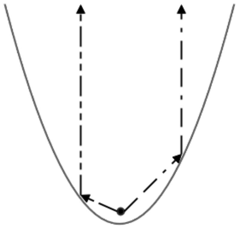
[0065] Such as Figure 7 As shown, this embodiment constructs a parabola with a width of 1 unit and a height of 1 unit, and then rotates the obtained parabola by 180 degrees to obtain a conical beam of light at a certain angle. The angle β of the conical light column calculated in this embodiment.

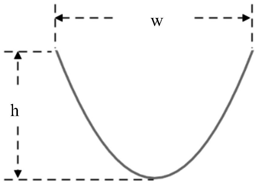
[0066] According to formula (1), the parabolic function with width w and height h is Substituting w as 1 and h as 1, the function of the parabola is obtained: y=4x 2

[0067] The focus of this parabola is: According to formula (2), the relationship between w, h and β is:

[0068]

[0069] Substitute:

[0070]

[0071]

Embodiment 2

[0073] In this embodiment, on the basis of Embodiment 1, the angle value of β is increased, assuming that β is increased to 90 degrees. In this embodiment, the value of h is calculated on the premise that w is fixed.

[0074] In order to increase the value of β, and also for the convenience of calculation, this embodiment fixes the width w of the parabola as 1 unit, and increases the value of β by changing the value of the height h of the parabola. According to formula (2), the relationship between w, h and β is:

[0075]

[0076] Substituting β to 90 and w to 1 into the above formula, we get:

[0077] After derivation and calculation, we get:

[0078] That is:

[0079] get:

[0080] Therefore, h=0.6. That is to say, when the width w remains unchanged and is still 1 unit, in order to obtain a conical beam with a β angle of 90 degrees, the height h of the parabola needs to be reduced.

Embodiment 3

[0082] In this embodiment, on the basis of Embodiment 1, by adding a light-proof and non-reflective baffle 1 to reduce β, assuming that the reduction β is 30 degrees. This embodiment calculates the value of L.

[0083] In order to reduce β to 30 degrees, according to the relationship between w, h, β and L in formula (3):

[0084]

[0085] Substituting w as 1, h as 1, and β as 30 into the above formula, we get:

[0086]

[0087]

[0088] After derivation and calculation, it is obtained: L=0.25. That is to say, when the width w and the height h are 1 unit, in order to obtain a conical light column with a β angle of 30 degrees, the length of the added opaque and non-reflective baffle 1 is 0.25 units, such as Figure 8 shown.


PUM


Abstract

The invention discloses a method for generating an arbitrary-angle cone light beam with distinguishing characteristics, which comprises the following steps: S1, constructing a parabola with the height h and the width w, putting the parabola in a rectangular coordinate system, and obtaining a parabola function expression when the origin of a coordinate axis is at the vertex of the parabola; s2, rotating the parabola around the symmetry axis of the parabola by 180 degrees to obtain a paraboloid with a reflection characteristic; s3, a light emitting source is arranged at the focus of the paraboloid, light emitted by the light emitting source is reflected by the paraboloid to obtain a conical light column with the angle beta, namely, the conical light column with any angle beta is obtained, and a bottom aperture of the conical light column has the distinguishing characteristic that the inner ring is bright and the outer ring is dark; the light sensing device can conveniently identify the light source and eliminate interference of other light sources; the device can generate a conical light beam with any angle, is suitable for different landing site environments, can prevent the visual detection distance of a system to an effective light source from being reduced, and reduces the later computer visual processing difficulty.

Description

technical field [0001] The present invention relates to a method for generating a cone of light with a different angle at any angle, and the cone of light acts as structured light for target guidance. Background technique [0002] In target guidance-related applications, for example, for multi-rotor UAV precision landing applications, structured light-based target guidance is a typical application requirement. However, due to the divergence of light and the influence of other light sources in the environment, if the effective emission angle of the light source at the landing point is not controlled, the system's visual detection distance of the effective light source will be reduced, and it will also increase the later computer vision. Dealing with difficulty. To this end, it is necessary to control the emission angle of the light source; moreover, in different application scenarios, it is also necessary to control the emission angle of the light source. , due to the diffe...

Claims


Application Information

Patent Timeline
Patent Type & Authority Applications(China)
IPC IPC(8): G02B27/00G06T7/80G06V20/10
Inventor 吴微
Owner HUAZHONG NORMAL UNIV
Why Eureka
Try Eureka