
Novel passive capacitance pen

A passive, capacitive pen technology, applied in the field of intelligent interaction and display, can solve problems such as damage to the pen head and the screen itself, small use angle, and insufficient smooth writing, so as to ensure smooth writing, prolong the service life, and ensure the writing feel.

Pending Publication Date: 2022-04-08
GUANGDONG HONGQIN COMM TECH CO LTD
View PDF0 Cites 0 Cited by
  • Summary
  • Abstract
  • Description
  • Claims
  • Application Information

AI Technical Summary

Problems solved by technology

Among them, conductive foam, conductive fiber and conductive cloth all have the problem of insufficient wear resistance to a certain extent, and the metal pen tip is easy to scratch the touch screen and the sound of hitting the screen is loud when writing, conductive silicone can effectively avoid it. Insufficient wear resistance and damage to the screen, and the impact sound of the screen is small, but limited by the characteristics of the material itself, the conductive silicone nib has a large damping when writing, the writing is not smooth enough, and it is easy to fatigue after long-term use
[0003] In addition, the nib and body of the passive capacitive pens currently used in electronic devices such as tablets are fixed, and the contact with the screen is in the form of sliding friction, resulting in relatively large friction, which will cause certain damage to the nib and the screen itself. small angle

Method used


Image

  • Novel passive capacitance pen
  • Novel passive capacitance pen
  • Novel passive capacitance pen

Examples


Embodiment Construction

[0025] Embodiments of the present invention will now be described with reference to the drawings, in which like reference numerals represent like elements. The orientation descriptions involved in the present invention, such as the orientation or positional relationship indicated by up, down, left, right, front, rear, etc., are all based on the orientation or positional relationship shown in the drawings, and are only for the convenience of describing the application. Technical solutions and / or simplified descriptions do not indicate or imply that the referred device or element must have a specific orientation, be constructed and operated in a specific orientation, and thus should not be construed as limiting the application. The first, second, etc. described are only used to distinguish technical features, and cannot be understood as indicating or implying relative importance, or implicitly indicating the number of indicated technical features, or implicitly indicating the seq...


PUM


Abstract

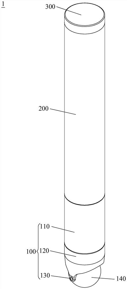
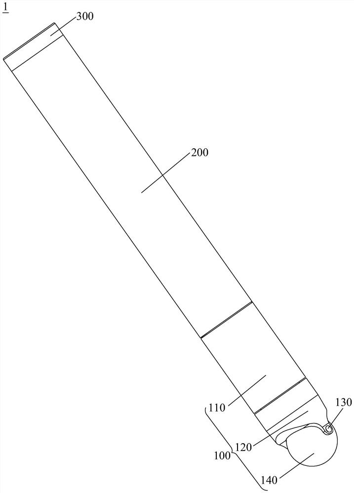
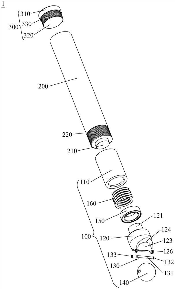
The invention discloses a novel passive capacitance pen which comprises a pen body, a pen cap and a pen point assembly. The pen cap and the pen point assembly are detachably connected to the two ends of the pen body. Wherein the pen point assembly comprises a connecting sleeve, a pen point end, a spherical pen point and an elastic piece, and the connecting sleeve is detachably connected to the pen body; one end of the pen point end is rotatably connected to the connecting sleeve, the other end of the pen point end protrudes out of the connecting sleeve and is connected with a pen point shaft, and the axial direction of the pen point shaft is perpendicular to the axial direction of a rotating shaft of the pen point end; the spherical pen point is rotatably connected to the pen point shaft; the elastic piece is contained in the connecting sleeve, and the two ends of the elastic piece abut against the pen point end and the pen body respectively. According to the novel passive capacitance pen, through rolling contact between the spherical pen point and a screen, the friction force between the spherical pen point and the screen is reduced, the service life of the screen and the capacitance pen is prolonged, and smooth writing is guaranteed through 360-degree rotation of the spherical pen point and damping and buffering of the elastic piece.

Description

technical field [0001] The invention relates to the fields of intelligent interaction and display, in particular to a novel passive capacitive pen. Background technique [0002] The principle of passive capacitive pens is to imitate the touch effect of fingers. The pen tip is a conductive material. When in contact with the touch screen, it can cause the capacitance change of the touch screen matrix. The pen tip materials of the popular passive capacitive pens on the market include conductive foam, metal, conductive fiber, Conductive cloth or conductive silicone, etc. Among them, conductive foam, conductive fiber and conductive cloth all have the problem of insufficient wear resistance to a certain extent, and the metal pen tip is easy to scratch the touch screen and the sound of hitting the screen is loud when writing, conductive silicone can effectively avoid it. Insufficient wear resistance and damage to the screen, and the impact sound of the screen is small, but limited...

Claims


Application Information

Patent Timeline
IPC IPC(8): G06F3/0354
Inventor 罗涛彭镇古尚贤
Owner GUANGDONG HONGQIN COMM TECH CO LTD
Learn More