Control method of self-starting permanent magnet synchronous motor
A technology of permanent magnet synchronous motor and control method, which is applied in the direction of motor generator control, AC motor control, electronic commutation motor control, etc., can solve the problems of low stability, difficult adjustment of flux linkage, high system cost, etc., and achieve high speed The effect of moment dynamic response
- Summary
- Abstract
- Description
- Claims
- Application Information
AI Technical Summary
Problems solved by technology
Method used
Image


Examples
Embodiment 1
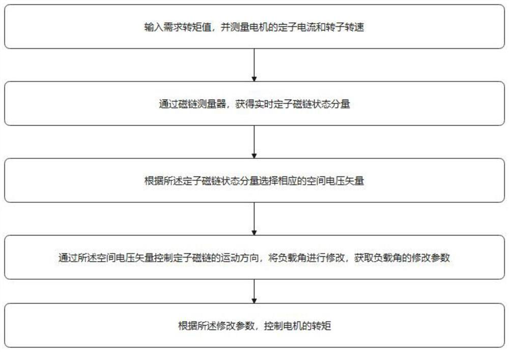
[0056] An embodiment of the present invention provides a control method for a self-starting permanent magnet synchronous motor, comprising the following steps:
[0057] Input the required torque value, and measure the stator current and rotor speed of the motor;
[0058] Obtain the real-time stator flux state quantity and real-time rotor flux state quantity through the flux linkage measuring device;
[0059] Change the state quantities of the real-time stator flux linkage and the real-time rotor flux linkage according to the required torque value, and control the motion direction of the real-time stator flux linkage and the real-time rotor flux linkage;
[0060] Change the inclination angle of the real-time stator flux linkage and the real-time rotor flux linkage, obtain the modified parameters of the inclination angle, and control the torque of the motor.
[0061] The working principle of the above-mentioned technical scheme is:
[0062]In the prior art of the present inven...
Embodiment 2
[0065] In an embodiment of the present invention: said inputting the required torque value and measuring the real-time stator current and real-time rotor speed of the motor include:
[0066] Determining the stator position signal of the motor through signal detection, performing current detection on the stator position, and obtaining the stator current;
[0067] The stator current is transmitted to a filter for signal filtering, and then input to an A / D conversion circuit for signal conversion to obtain a current digital signal;
[0068] The rotational speed of the rotor is obtained by a speedometer.
[0069] The working principle of the above-mentioned technical scheme is:
[0070] In the prior art of the present invention, the stator position is calculated by a control algorithm, but the accuracy of this algorithm is not enough, and the calculated value often has deviations. The present invention determines the stator position signal of the motor through signal detection, a...
Embodiment 3
[0073] In an embodiment of the present invention: the obtaining of the real-time stator flux state quantity and the real-time rotor flux state quantity through the flux linkage measuring device includes:
[0074] Obtain the amplitude and phase of the real-time stator flux linkage through the measurement results of the flux linkage measuring device;
[0075] Obtain the amplitude and phase of the real-time rotor flux linkage through the measurement results of the flux linkage measuring device;
[0076] According to the amplitude and phase of the real-time stator flux and the real-time rotor flux, state parameters of the stator flux and the rotor flux are extracted.
[0077] The working principle of the above-mentioned technical scheme is:
[0078] In the prior art of the present invention, in the relatively static coordinate system of the mathematical model, the stator flux and rotor flux coordinate systems are established, and the amplitude and phase of the connection between ...
PUM
 Abstract
Description
Claims
Application Information
PatSnap Eureka turns technology decisions into work you can execute. Powered by our Innovation Knowledge Graph, it runs expert workflows across engineering, life sciences, materials and intellectual property. Get your review-ready output in minutes.


