
Heat dissipation device and electronic equipment

A technology of heat dissipation device and installation cavity, applied in the direction of cooling/ventilation/heating transformation, etc., can solve the problem of poor heat dissipation effect of heat dissipation device

Pending Publication Date: 2022-04-08
SUZHOU LANGCHAO INTELLIGENT TECH CO LTD
View PDF0 Cites 0 Cited by
  • Summary
  • Abstract
  • Description
  • Claims
  • Application Information

AI Technical Summary

Problems solved by technology

[0003] Therefore, the technical problem to be solved by the present invention is to overcome the defect of poor heat dissipation effect of the heat dissipation device in the prior art, thereby providing a heat dissipation device and electronic equipment that prevent the backflow of hot air and ensure good heat dissipation effect

Method used


Image

  • Heat dissipation device and electronic equipment
  • Heat dissipation device and electronic equipment
  • Heat dissipation device and electronic equipment

Examples


Embodiment Construction

[0032] The technical solutions of the present invention will be clearly and completely described below in conjunction with the accompanying drawings. Apparently, the described embodiments are some of the embodiments of the present invention, but not all of them. Based on the embodiments of the present invention, all other embodiments obtained by persons of ordinary skill in the art without making creative efforts belong to the protection scope of the present invention.

[0033] In the description of the present invention, it should be noted that the terms "center", "upper", "lower", "left", "right", "vertical", "horizontal", "inner", "outer" etc. The indicated orientation or positional relationship is based on the orientation or positional relationship shown in the drawings, and is only for the convenience of describing the present invention and simplifying the description, rather than indicating or implying that the referred device or element must have a specific orientation, ...


PUM


Abstract

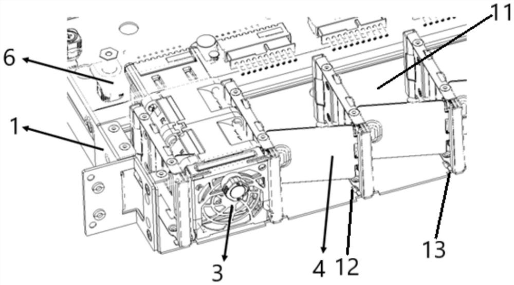
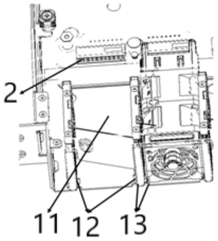
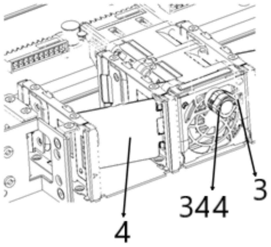
The invention relates to the technical field of heat dissipation devices, in particular to a heat dissipation device and electronic equipment. The heat dissipation device comprises a case, a connector, a fan module and a wind shielding structure, wherein a plurality of fan mounting cavities are formed in the case; the connector is connected with the case and is positioned at one end of the fan mounting cavity; the fan module is suitable for being detachably mounted in the fan mounting cavity from the other end of the fan mounting cavity and is suitable for being connected with the connector; the air blocking structure is rotatably connected to the cavity wall of the fan installation cavity and is provided with a closing position for closing the fan installation cavity after the fan module is disassembled and an opening position for opening the fan installation cavity when the fan module is installed. According to the heat dissipation device provided by the invention, when the fan module in one fan mounting cavity is disassembled, the wind shielding structure is located at the closed position, the fan mounting cavity is closed, and hot air dissipated by the fan modules in other fan mounting cavities is prevented from flowing back to the position to be cooled through the fan mounting cavity without the fan module.

Description

technical field [0001] The invention relates to the technical field of heat dissipation devices, in particular to a heat dissipation device and electronic equipment. Background technique [0002] In recent years, with the rapid development of Internet technology, especially the breakthrough of key technologies such as big data and cloud platform, the demand for servers is increasing. The heat dissipation problem in the server is also becoming more and more prominent. The heat dissipation of the server is inseparable from the heat dissipation device. The heat dissipation device generally includes a chassis and multiple sets of fan modules. The chassis is provided with multiple fan installation cavities, and each fan installation cavity can be connected to a set of fan modules. However, when no fan module is installed in the corresponding fan installation chamber, the hot air discharged from other fan modules is likely to flow back to the components to be cooled through the f...

Claims


Application Information

Patent Timeline
Patent Type & Authority Applications(China)
IPC IPC(8): H05K7/20
CPCY02D10/00
Inventor 梁安刚
Owner SUZHOU LANGCHAO INTELLIGENT TECH CO LTD
Learn More