Novel short MPO connector

A connector and a new type of technology, applied in the field of new short MPO connectors, can solve the problems of small applicable environment, unfavorable promotion and application, poor compatibility, etc., and achieve the effect of strong matching effect, reduced space occupancy, and strong versatility

Active Publication Date: 2020-09-25
汇聚科技(惠州)有限公司 +1
View PDF8 Cites 0 Cited by
  • Summary
  • Abstract
  • Description
  • Claims
  • Application Information

AI Technical Summary

Problems solved by technology

[0003] In the prior art, the general-purpose MPO connector mainly consists of MT ferrule, outer shell, inner shell, socket, spring, pressure ring, net tail and guide pin seat, and the length is reduced from 60mm to 43mm and 38mm, but For high-density optical fiber application environments such as data centers, the 38mm long MPO connector cannot meet the full application requirements. If a special ultra-short MPO connector is used, its applicable environment range is small, the cost is high, and the compatibility is poor, which is not conducive to popularization and application. So how to design a Compatible with existing MPO connection methods, cost-effective, and shorter connectors are an urgent need for the current MPO development

Method used


Image

  • Novel short MPO connector
  • Novel short MPO connector
  • Novel short MPO connector

Examples


Embodiment 1

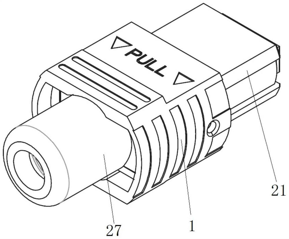
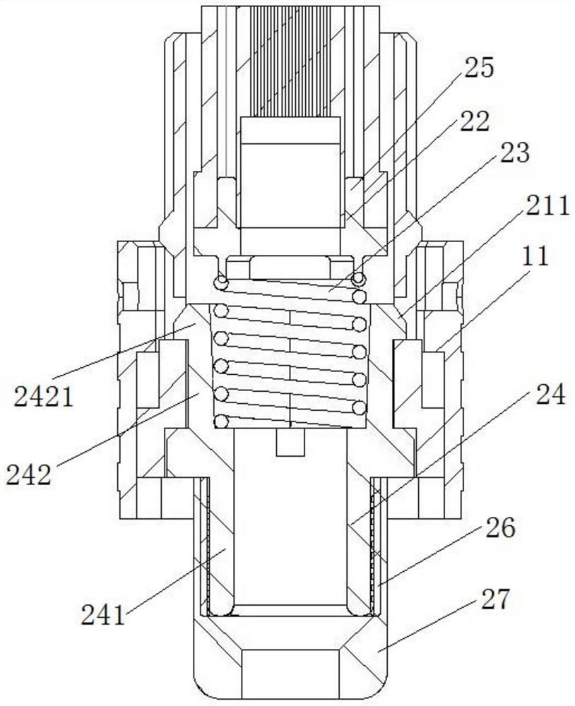
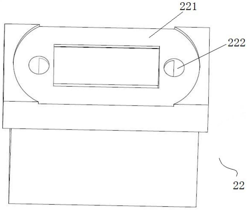
[0036] Such as Figure 1-Figure 5 As shown, a new type of short MPO connector is provided, which includes an outer shell and a connector body. The outer shell can be axially movably sleeved on the connector body. The connector body includes an inner shell, and the inner shell is sequentially provided with MT Ferrule, push spring, socket, press buckle and net tail; the tail of MPO connector is fixed on the cable by press buckle and net tail; the bottom of MT ferrule is provided with a concave table that matches the shape of the push spring , There are counterbore holes on both sides of the concave table, guide pins are pierced in the counterbore holes, and guide pin steps matching the counterbore are provided at the bottom of the guide pins, and the push spring presses the bottom of the guide pins; the inner shell and An unlocking spring accommodating cavity is arranged between the outer shells; an unlocking spring is fixedly arranged in the unlocking spring accommodating cavit...

Embodiment 2

[0044] This example is similar to Embodiment 1, the difference is that, as Figure 6 As shown, in this example, two unlocking grooves II are provided on the front and rear sides of the inner wall of the inner shell and the inner wall of the outer shell, forming four unlocking spring accommodation chambers, and the four unlocking spring accommodation chambers are respectively provided with unlocking springs. The unlocking spring is a linear cylindrical spring; the length of the unlocking groove II is L3, and the interval of L3 is 3mm≤L3≤5mm. In this example, the length L3 of the unlocking groove II is 4 mm. Moving the unlocking spring to the front and back of the inner casing can increase the thickness of the front and rear side walls of the inner casing, and prevent the inner casing from cracking when the socket is pulled sideways.

[0045] The number of linear cylindrical springs is 4, which are respectively arranged on both sides of the front side and the rear side of the i...

Embodiment 3

[0047] This example is similar to Embodiment 1, the difference is that, as Figure 7 and Figure 8 As shown, the front and rear surfaces of the tail end of the inner housing are provided with a limit key two, the limit key two is a tail end flange, and an unlocking spring accommodation chamber is formed between the limit key two and the tailstock of the inner housing, and the unlocking spring accommodates The cavity is fixed with an unlocking spring, and the unlocking spring is a spring in the shape of a dovetail clip; the lateral thickness of the limit key 2 is L4, and the interval of L4 is 0.3mm≤L4≤0.6mm. In this example, the transverse thickness L4 of the limit key 2 is 0.4mm, and the height L7 of the buckle is 4mm.

[0048] Specifically, in the vertical direction, the tail end flange of the inner casing and the tailstock of the inner casing form a slot space, and the spring can be directly snapped into the slot to provide a fixed support for the unlocking spring. Yes, in...


PUM

PropertyMeasurementUnit
Lengthaaaaaaaaaa

Abstract

The invention relates to the technical field of MPO connectors, and particularly discloses a novel short MPO connector. The connector main body comprises an inner shell, an MT insertion core, a pushing spring and an insertion frame are sequentially arranged in the inner shell, and a pressing buckle and a net tail are arranged at the tail of the insertion frame. The tail part of the MPO connector and the net tail are fixed on the cable through the pressing buckle; the bottom of the MT insertion core is provided with a concave platform matched with the pushing spring in shape, counter bores areformed in the two sides of the concave platform respectively, guide pins are arranged in the counter bores in a penetrating mode, guide pin steps matched with the counter bores are arranged at the bottoms of the guide pins, and the pushing spring abuts against the bottoms of the guide pins. An unlocking spring accommodating cavity is formed between the inner shell and the outer shell; and an unlocking spring is fixedly arranged in the unlocking spring accommodating cavity. Compared with an existing MPO connector, the size of the MPO connector is greatly reduced, the assembly difficulty is reduced, the production cost of the MPO connector can be effectively saved, the appearance structure of the MPO connector is similar to that of an existing MPO connector, the requirement of a general typeMPO on the existing market can be met, and a special adapter and an installation cabinet are not needed.

Description

technical field [0001] The invention relates to the technical field of MPO connectors, in particular to a novel short MPO connector. Background technique [0002] MPO is a multi-core optical fiber connector, which is one of the important passive components to realize the connection of optical fiber cables. It has been widely used in many projects and plays an important role in optical fiber transmission systems. With the advent of the information age, along with the trend of wider and wider coverage of optical fiber, optical fiber cabling is gradually developing towards the requirements of dense, miniaturized, and simplified construction. This puts forward higher requirements for MPO connectors. While ensuring stable performance, small MPO connectors with higher fiber outlet density, convenient installation, better cost performance, and good compatibility are important trends in future development. [0003] In the prior art, the general-purpose MPO connector mainly consists...

Claims


Application Information

Patent Timeline
IPC IPC(8): G02B6/38
CPCG02B6/3826G02B6/3885
Inventor 汪伟方炜安晓勇齐义国高亮陈伟峰卢慧叶斌郑钟信欧阳艳
Owner 汇聚科技(惠州)有限公司
Why Eureka
Try Eureka