Design method of efficient and energy-saving stirrer impeller

A high-efficiency, energy-saving, design method technology, applied to mixers with rotating stirring devices, chemical instruments and methods, mixers, etc., can solve the problems of lack of targeted impeller design, failure to achieve high efficiency and energy saving effects, and single fixed structure. , to achieve high economic benefits and promotion value, energy-saving promotion, and the effect of improving work efficiency

Pending Publication Date: 2022-04-12
江苏双月环保设备有限公司
View PDF0 Cites 0 Cited by
  • Summary
  • Abstract
  • Description
  • Claims
  • Application Information

AI Technical Summary

Problems solved by technology

[0005] Aiming at the deficiencies of the prior art, the present invention provides a high-efficiency and energy-saving mixer impeller design method, which solves the problem that the traditional mixer impeller generally adopts a single fixed structure and lacks targeted impeller design. By adjusting the relative thickness, cross-sectional shape, surface The adjustment methods such as roughness cannot achieve the expected high efficiency and energy saving effect

Method used


Image

  • Design method of efficient and energy-saving stirrer impeller
  • Design method of efficient and energy-saving stirrer impeller
  • Design method of efficient and energy-saving stirrer impeller

Examples


Embodiment

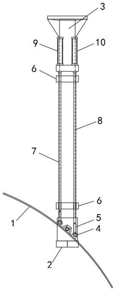
[0025] Such as figure 1 As shown, a high-efficiency and energy-saving mixer impeller design method proposed by an embodiment of the present invention is to improve the design on the existing mixer impeller structure including airfoil blade 1, wheel base 2 and rotating shaft 3. The high-efficiency and energy-saving mixer impeller The design methodology includes the following steps:

[0026] S1. Connect the airfoil blade 1 to the wheel seat 2 in rotation, and set a shaft connection seat 4 on the left and right sides of the corresponding wheel seat 2 connection end on the airfoil blade 1, and connect a movable seat 4 to the two shaft connection seats 4 respectively. axis 5;

[0027] S2. A positioning disc 6 is arranged at the upper and lower ends of the rotating shaft 3, and the first transmission rod 7 and the second transmission rod 8 respectively connected to the two movable shafts 5 are arranged longitudinally between the upper and lower positioning discs 6. Through the posi...


PUM


Abstract

The invention belongs to the technical field of stirrers, and particularly relates to a high-efficiency energy-saving stirrer impeller design method which comprises the following steps: S1, shaft connecting seats connected with movable shafts are arranged on the left side and the right side, corresponding to a wheel seat connecting end, of a wing-shaped blade; s2, positioning discs are arranged at the upper end and the lower end of the rotating shaft, and a first transmission rod and a second transmission rod which are rotationally connected with the two movable shafts are arranged between the two positioning discs; and S3, a first lifting driving piece and a second lifting driving piece are installed on the rotating shaft, and driving rods of the first lifting driving piece and the second lifting driving piece are connected with the top ends of the first transmission rod and the second transmission rod correspondingly. An existing fixed impeller structure is optimized into the impeller structure with the adjustable attack angle, the stress of the wing-shaped blades is adjusted by adjusting the included angles between the faces of the wing-shaped blades and fluid, and the purpose of improving the working efficiency of the impeller by increasing the stress of the wing-shaped blades is achieved. On the contrary, the energy-saving effect is achieved by reducing the stress of the airfoil

Description

technical field [0001] The invention relates to the technical field of mixers, in particular to a high-efficiency and energy-saving mixer impeller design method. Background technique [0002] The impeller of the mixer is an important part of the mixer, and the quality of the impeller is one of the important conditions affecting the energy saving and working efficiency of the mixer. The impeller usually consists of a wheel base and blades. The wheel base is connected to the rotating shaft, and the blades are installed on the impeller. During operation, the motor drives the rotating shaft to rotate, thereby driving the wheel base and the blades on it to rotate, and stirring the fluid in the container. [0003] In order to improve the mixing effect, the existing improvement methods are generally achieved by adjusting the relative thickness, cross-sectional shape, surface roughness, etc. of the blades, but the traditional mixer impeller generally adopts a single fixed structure,...

Claims


Application Information

Patent Timeline
Patent Type & Authority Applications(China)
IPC IPC(8): B01F27/054B01F27/1152
Inventor 刘涛孟辉
Owner 江苏双月环保设备有限公司
Why Eureka
Try Eureka