Improved cutter and improvement method thereof

An improved, cutting tool technology, applied in drilling tool accessories, manufacturing tools, drilling/drilling equipment, etc., can solve the problems of low tool life, sticking to aluminum, poor finish and other problems of straight fluted cutting tools, so as to increase the life of the tool. Effect

Pending Publication Date: 2022-04-12
爱三(佛山)汽车部件有限公司
View PDF0 Cites 0 Cited by
  • Summary
  • Abstract
  • Description
  • Claims
  • Application Information

AI Technical Summary

Problems solved by technology

[0004] The tools used for machining the shaft hole on the side seat of the motor are all straight grooved blades. The normal life of the straight grooved blades is between 20,000 and 40,000. The smoothness requirement is within Ra1.6. The straight grooved blades are mainly due to The poor finish is replaced, and the replaced tool with poor finish is basically caused by sticking aluminum after the outer diameter is worn, and the service life of the straight flute tool is generally relatively low

Method used


Image

  • Improved cutter and improvement method thereof

Examples


Embodiment 1

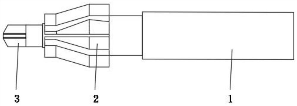
[0027] see figure 1 , an embodiment provided by the present invention: an improved knife, including a handle 1, a first blade 2 and a second blade 3, one end of the handle 1 is provided with a second blade 3, one side of the second blade 3 The handle 1 is provided with a first blade 2, the φ25 and φ22 of the first blade 2 are respectively 10-degree spiral grooves, the φ10.1 of the second blade 3 is a straight groove, and the first blade 2 and the second blade 3 are respectively Six blades, the coating on the first blade 2 and the second blade 3 is HA-DLC.

[0028] The aperture obtained during the use of the first blade 2 and the second blade 3 is consistent with the standard aperture, and the finish is required to be within Ra1.3, and the finish can still be kept within the acceptable range until the aperture is small, and the service life is between 50,000 and 50,003. time, increase life expectancy.

Embodiment 2

[0030] An embodiment provided by the present invention: an improved method for an improved tool, the unimproved solution:

[0031] The φ25 and φ22 of the first blade 2 and the φ10.1 of the second blade 3 are both straight grooves. The normal service life of the first blade 2 and the second blade 3 is between 20,000 and 40,000, and the smoothness requirement is within Ra1.6. If the finish requirement exceeds Ra1.6, it needs to be replaced;

[0032] The first improvement plan:

[0033] The φ25 and φ22 of the first blade 2 and the φ10.1 of the second blade 3 are respectively changed into 10-degree spiral grooves;

[0034] The diameter of the first blade 2 and the second blade 3 obtained during use is larger than the standard aperture. The φ10.1 of the second blade 3 is changed to a 10-degree spiral groove, and the blade core of the second blade 3 is too thick to cause vibration. ;

[0035] The second improvement plan:

[0036] The φ25 and φ22 of the first blade 2 are changed ...


PUM


Abstract

The invention relates to the technical field of cutters, in particular to an improved cutter and an improvement method thereof. According to the technical scheme, the cutter comprises a cutter handle, first cutting edges and second cutting edges, the second cutting edges are arranged at one end of the cutter handle, the first cutting edges are arranged on the cutter handle on one side of the second cutting edges, phi 25 and phi 22 of the first cutting edges are respectively 10-degree spiral grooves, phi 10.1 of the second cutting edges is a straight groove, the number of the first cutting edges and the number of the second cutting edges are respectively six, and the number of the first cutting edges and the number of the second cutting edges are respectively six. The coatings on the first cutting edge and the second cutting edge are made of HA-DLC. The blade core of the second blade with the straight groove cannot cause vibration, the aperture obtained in the using process of the first blade with the 10-degree spiral groove is consistent with the standard aperture, the finish degree is required to be within Ra1.3, the finish degree can still be kept within the qualified range until the aperture is small, the service life ranges from 50,000 to 50,000 3, and the service life is prolonged.

Description

technical field [0001] The invention relates to the technical field of cutting tools, in particular to an improved cutting tool and an improving method thereof. Background technique [0002] A cutting tool is a tool used for cutting in mechanical manufacturing, also known as a cutting tool. The vast majority of knives are for machine use, but some are also for hand use. Since the knives used in mechanical manufacturing are basically used to cut metal materials, the term "knife" is generally understood as a metal cutting tool. Knives for cutting wood are called woodworking knives. There is also a special category of cutting tools for geological exploration, well drilling, and mine drilling, called mine cutting tools. [0003] Tools can be divided into five categories according to the surface of the workpiece: tools for processing various external surfaces include turning tools, planers, milling cutters, external surface broaches and files, etc.; hole processing tools inclu...

Claims


Application Information

Patent Timeline
IPC IPC(8): B23B51/00
Inventor 杨旭光冯子健韦朝江周志文叶永潮麦福震杨智展张少煌
Owner 爱三(佛山)汽车部件有限公司
Why Eureka
Try Eureka