Separated fluorescent light

A fluorescent lamp and separate technology, applied in the field of fluorescent lamps, can solve the problems of impossible recycling, increased manufacturing cost, use cost, increased energy consumption, material consumption and labor consumption, etc., to achieve the highest conversion efficiency, reduce the total burden, Effects that are easy to handle separately

Inactive Publication Date: 2005-07-27
吴玉书
View PDF1 Cites 1 Cited by
  • Summary
  • Abstract
  • Description
  • Claims
  • Application Information

AI Technical Summary

Problems solved by technology

According to the current technology, the fluorescent lamp manufactured by this method will inevitably have many problems because the filament, electronic powder, inert gas, fluorescent powder, activator, adhesive, etc. are all concentrated in a glass tube. Congenital deficiencies and defects: 1. From the perspective of process design, due to the characteristics of low-pressure mercury vapor discharge, the thermal stability of phosphor crystals, the damage and failure of fluorescent crystal lattices by strong ultraviolet radiation, the limited luminescence per unit area of ​​fluorescent substances, etc. Therefore, it is impossible to achieve ideal and unified important technical indicators such as high power, high electro-optical conversion efficiency, high luminous flux, high color rendering, and long life. It is often emphasized that one of the indicators must be sacrificed by the other or even several 2. Because in the products produced by the integrated design, whether it is the damage of the filament, the sputtering failure of the electronic powder, or the failure of the light decay of the phosphor powder, the whole lamp will be discarded (the energy-saving lamp will be electronically towned. The flow device is also combined in the whole, which increases the probability of discarding the whole lamp), from the perspective of the whole society, it increases the manufacturing cost, the use cost, increases the energy consumption, material consumption, labor consumption, and reduces the efficiency; 3. Due to the electronic Powder, fluorescent powder, adhesive, and toxic heavy metal mercury are mixed together, which makes it easier to consume electronic powder in advance, "poison" the fluorescent powder, and shorten the effective life of the whole lamp. Separation is extremely difficult, and recycling becomes extremely impossible, which also causes strong environmental pollution; 4. Because in the integrated manufacturing process, the lamp cavity must undergo a high vacuum process to withstand the external high pressure process, plus the gas Discharge special requirements, so all lamp chambers must be tubular or tubular (such as U-shaped, ring-shaped, spiral, etc.), but no matter from the perspective of optical principles or practical applications, it is difficult to achieve the ideal luminous effect (effective Partial loss of luminous flux) and visual effects
After searching, the application number is 90203413, and the name is "High-performance Electronic Fluorescent Lamp Separated Luminaire". It only sets the components of the electronic ballast in two separate housings, and does not separate the ultraviolet light generating device from the visible light conversion device. , so the above defects still exist and cannot be ruled out; the application number is 01141186

Method used


Image

  • Separated fluorescent light

Examples


Embodiment Construction

[0008] Embodiments are further described in detail below in conjunction with accompanying drawings

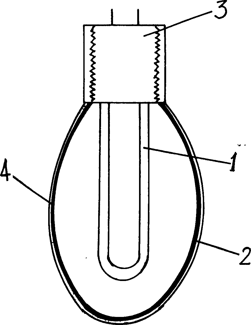
[0009] refer to figure 1 , 1-ultraviolet generating device; 2-visible light conversion device; 3-lamp holder; 4-fluorescent adhesion layer. As shown in the figure, the ultraviolet generating device (1) is composed of a closed quartz glass tube with good ultraviolet permeability. There is an extractable solid metal core (usually a copper core) in the tube, and the inner core of the tube is connected with a filament with electronic powder. The outer core end of the tube is electrically connected to the output end of the ballast, and the end of the ultraviolet generating device (1) is fixedly connected to the lamp holder (3); the tube is filled with a certain amount of metal mercury, and the quartz tube is vacuumed and injected with an appropriate amount of inert gas. Produces large amounts of intense UV light. The ultraviolet light passes through the wall of the quartz tube and...


PUM


Abstract

The invention is related to a separable structure that is used in the illuminator of the fluorescent lamp. It consists of ultraviolet ray generator and visible light switching device. The visible light switching device is connected with lamp base. The ultraviolet ray generator is connected with lamp base.

Description

technical field [0001] The invention relates to a lighting appliance, in particular to a fluorescent lamp with a detachable ultraviolet generating device and a visible light converting device. Background technique [0002] In the past, all products that produced fluorescent electric light sources, such as ordinary fluorescent lamps and trichromatic fluorescent lamps (energy-saving lamps), used a method in which ultraviolet generators and phosphors (conversion sources from ultraviolet to visible light) were combined in one lamp tube. According to the current technology, the fluorescent lamp manufactured by this method will inevitably have many problems because the filament, electronic powder, inert gas, fluorescent powder, activator, adhesive, etc. are all concentrated in a glass tube. Congenital deficiencies and defects: 1. From the perspective of process design, due to the characteristics of low-pressure mercury vapor discharge, the thermal stability of phosphor crystals, t...

Claims


Application Information

Patent Timeline
Patent Type & Authority Applications(China)
IPC IPC(8): H01J5/50H01J61/00
Inventor 吴玉书
Owner 吴玉书
Why Eureka
Try Eureka