Numerical control hydraulic plate shearing machine

A technology of hydraulic shear and plate machine, which is applied in shearing machine equipment, shearing device, accessories of shearing machine, etc., can solve problems such as sheet scratches, and achieve the effect of preventing impact

Pending Publication Date: 2022-04-12
徐家兴
View PDF0 Cites 1 Cited by
  • Summary
  • Abstract
  • Description
  • Claims
  • Application Information

AI Technical Summary

Problems solved by technology

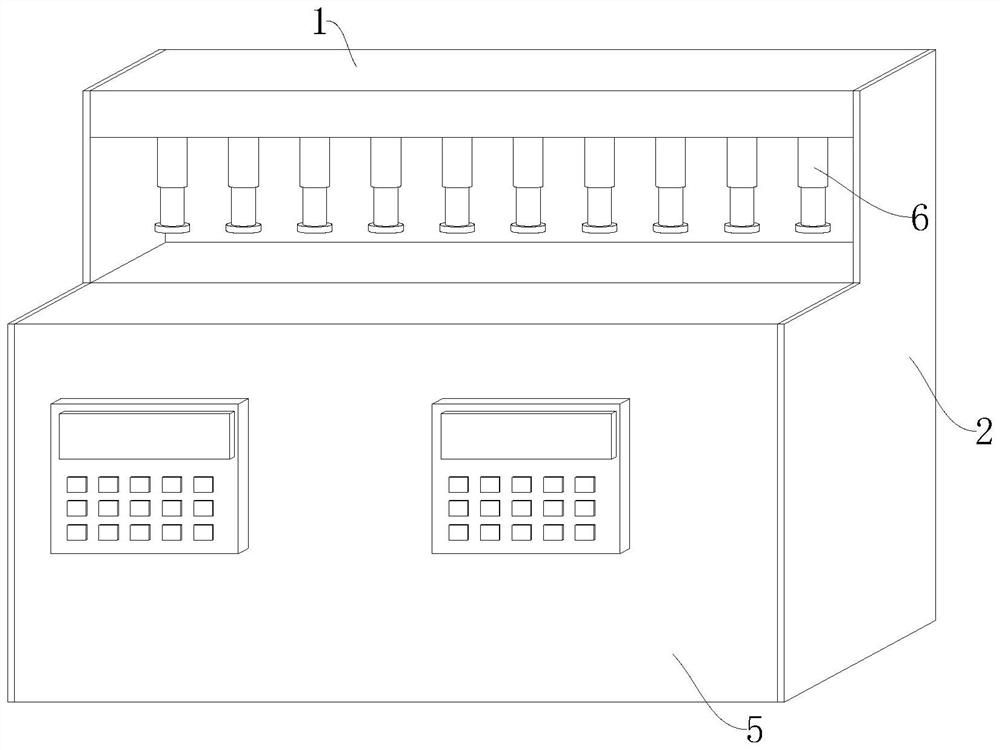
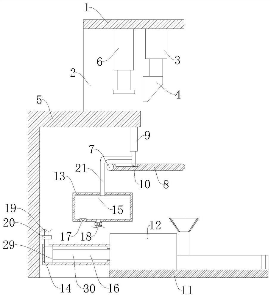
[0005] The purpose of the present invention is to provide a numerically controlled hydraulic plate shearing machine to solve the problem that the plate will be scratched when the sheared plate falls on the surface of other plates proposed in the background art

Method used


Image

  • Numerical control hydraulic plate shearing machine
  • Numerical control hydraulic plate shearing machine
  • Numerical control hydraulic plate shearing machine

Examples


Embodiment Construction

[0041] The following will clearly and completely describe the technical solutions in the embodiments of the present invention with reference to the accompanying drawings in the embodiments of the present invention. Obviously, the described embodiments are only some, not all, embodiments of the present invention. Based on the embodiments of the present invention, all other embodiments obtained by persons of ordinary skill in the art without making creative efforts belong to the protection scope of the present invention.

[0042] In describing the present invention, it is to be understood that the terms "center", "longitudinal", "transverse", "length", "width", "thickness", "upper", "lower", "front", " Back", "Left", "Right", "Straight", "Horizontal", "Top", "Bottom", "Inner", "Outer", "Clockwise", "Counterclockwise", etc. or The positional relationship is based on the orientation or positional relationship shown in the drawings, which is only for the convenience of describing t...


PUM


Abstract

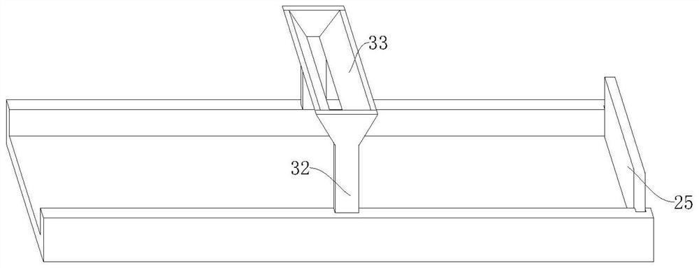
The invention relates to the technical field of plate shearing machines, in particular to a numerical control hydraulic plate shearing machine which comprises a first mounting plate, wall plates are vertically and fixedly mounted at the two ends of the first mounting plate, a first hydraulic rod is fixedly mounted on the bottom wall of the first mounting plate, and a plate shearing knife is fixedly mounted at the output end of the first hydraulic rod. The bracket rotates around the mounting rod under the action of gravity, and the included angle between the bracket and the horizontal plane is gradually increased in the rotating process, so that the gliding force borne by a plate on the surface of the bracket is gradually increased, and the plate slides along the bracket and falls into the storage bin on the collecting box; and the collecting box moves along the guide rail under the action of the driving mechanism, so that each cut plate falls into an independent storage bin, and the situation that the cut plates collide with one another and are damaged can be prevented.

Description

technical field [0001] The invention relates to the technical field of shearing machines, in particular to a numerically controlled hydraulic shearing machine. Background technique [0002] The hydraulic shearing machine is a kind of machine that uses the moving upper blade and the fixed lower blade to apply a shearing force to the metal sheets of various thicknesses by using a reasonable blade gap, so that the sheets are broken and separated according to the required size. The shape classification of scissors is divided into straight knife shears and disc knife shears. Straight knife shears are divided into gantry shears and throat shears according to their structure. Disc knife shears are divided into disc shears, rolling shears, multi-disc shears and rotary trimming shears according to their structure. [0003] The plates cut by the existing shearing machine during the working process directly fall to the ground. Since the position of the shearing machine is fixed, and ...

Claims


Application Information

Patent Timeline
Patent Type & Authority Applications(China)
IPC IPC(8): B23D15/14B23D33/00
Inventor 徐家兴刘书凯
Owner 徐家兴
Why Eureka
Try Eureka