Gear shaper with adjustable cutter spacing

A gear shaping machine and tool position technology, which is applied to gear cutting machines, gear teeth, mechanical equipment, etc., can solve the problems of inaccurate precision and low efficiency, and achieve the effect of accurate adjustment size, simple structure, and convenient vertical position adjustment.

Active Publication Date: 2022-04-12
WENLING MINGHUA GEAR
View PDF7 Cites 0 Cited by
  • Summary
  • Abstract
  • Description
  • Claims
  • Application Information

AI Technical Summary

Problems solved by technology

[0005] The purpose of the present invention is to provide a gear shaper with knife position adjustment for the technical p

Method used


Image

  • Gear shaper with adjustable cutter spacing

Examples


Embodiment Construction

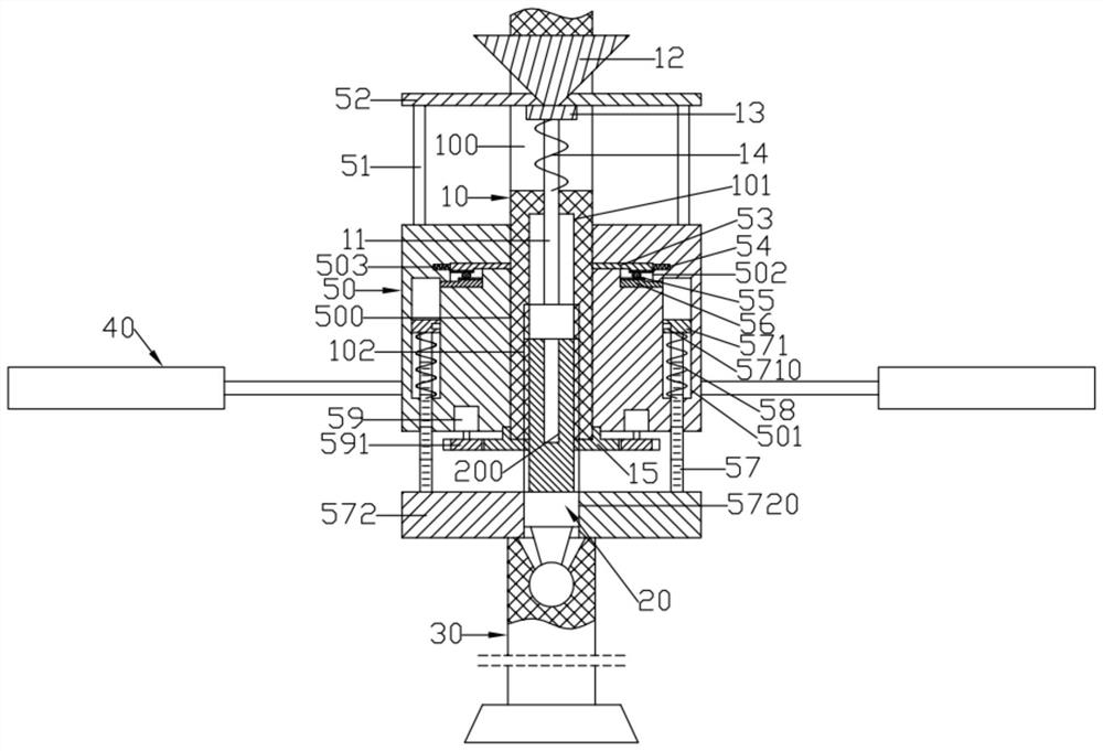
[0015] Such as figure 1 As shown, a gear shaping machine for adjusting the cutter position includes a swing rod 10, a ball tie rod 20, a cutter shaft 30 and a pair of left and right symmetrically arranged cutter position adjustment seats 50; the bottom ball head of the ball pull rod 20 is connected to the cutter shaft 30 and the diameter of the ball tie rod 20 is smaller than the diameter of the cutter shaft 30; the swing rod 10 is fixed on the gear shaping machine frame; the bottom surface of the swing rod 10 is formed with a lifting screw hole 102; Gear 15; the center of the lifting gear 15 is formed with a driving threaded hole; the upper part of the ball tie rod 20 is screwed into the lifting threaded hole 102 and the driving threaded hole; and the right side; the end faces of a pair of knife position adjustment seats 50 that are close to each other are respectively formed with semi-cylindrical groove-shaped upper slots 500 with upper and lower openings; the diameter of th...


PUM


Abstract

The invention discloses a gear shaping machine capable of adjusting a cutter position. A lifting threaded hole is formed in the bottom surface of a swing rod; a lifting gear is pivoted to the bottom face of the swing rod. A driving threaded hole is formed in the center of the lifting gear; the upper part of the ball pull rod is screwed in the lifting threaded hole and the driving threaded hole; semi-cylindrical groove-shaped upper insertion grooves with upper openings and lower openings are formed in the end faces, close to each other, of the pair of cutter position adjusting seats correspondingly; a lifting driving motor is fixed on the bottom surface of the cutter position adjusting seat; lifting driving gears are fixed at the lower ends of output shafts of the lifting driving motors; a vertical connecting rod is vertically and telescopically arranged on the bottom surface of the cutter position adjusting seat; a lower limiting seat is formed at the bottom of the vertical connecting rod; semi-cylindrical groove-shaped lower limiting grooves with upper and lower openings are formed in the end faces, close to each other, of the pair of lower limiting seats correspondingly. The vertical connecting rod is provided with scale marks in the vertical direction.

Description

technical field [0001] The invention relates to the technical field of gear shaping machines, in particular to a gear shaping machine with tool position adjustment. Background technique [0002] At present, manual adjustment is mostly used for the up and down adjustment of the gear shaping cutter of the gear shaping machine at home and abroad. This method has the following disadvantages: [0003] 1. It is necessary to climb high for operation, which increases the risk of the operator's work; [0004] 2. The adjustment accuracy is inaccurate and requires repeated adjustment and measurement to complete, so the adjustment efficiency is low. Contents of the invention [0005] The object of the present invention is to provide a gear shaping machine with knife position adjustment to solve the technical problems of low efficiency and inaccurate precision in manually adjusting the upper and lower positions of the gear shaping cutter. [0006] The technical solution of the presen...

Claims


Application Information

Patent Timeline
IPC IPC(8): B23F23/00B23F23/12
Inventor 洪军张新超黄振
Owner WENLING MINGHUA GEAR
Why Eureka
Try Eureka