Polishing shaft for flexibly cleaning casting blank

A technology for cleaning castings and grinding shafts, applied in the field of grinding shafts, can solve problems such as incomplete function of parts, damaged parts, unclean grinding of burrs, etc., and achieve the effect of ensuring air tightness

Inactive Publication Date: 2022-04-12
SUZHOU MINGZHI TECH
View PDF10 Cites 2 Cited by
  • Summary
  • Abstract
  • Description
  • Claims
  • Application Information

AI Technical Summary

Problems solved by technology

However, when grinding burrs, there are requirements for the pressure that one end of the grinding cloth or grinding wheel on the rotating shaft contacts the surface of the part. If the pressure of one end of the grinding cloth or grinding wheel contacting the surface of the part is too high, the part will be damaged, and the end of the grinding cloth or grinding wheel will be damaged. If the pressure contacting the surface of the part is too small, the burrs may not be polished cleanly, especially when the surface of the part has uneven patterns or characteristics. The patterns or features are directly erased, which will directly lead to the incomplete function of the part. Therefore, in this case, it is necessary to drive the grinding cloth or the grinding wheel to be installed on the rotating shaft to have a certain angle range relative to the surface of the part to be deburred.

Method used


Image

  • Polishing shaft for flexibly cleaning casting blank
  • Polishing shaft for flexibly cleaning casting blank
  • Polishing shaft for flexibly cleaning casting blank

Examples


Embodiment Construction

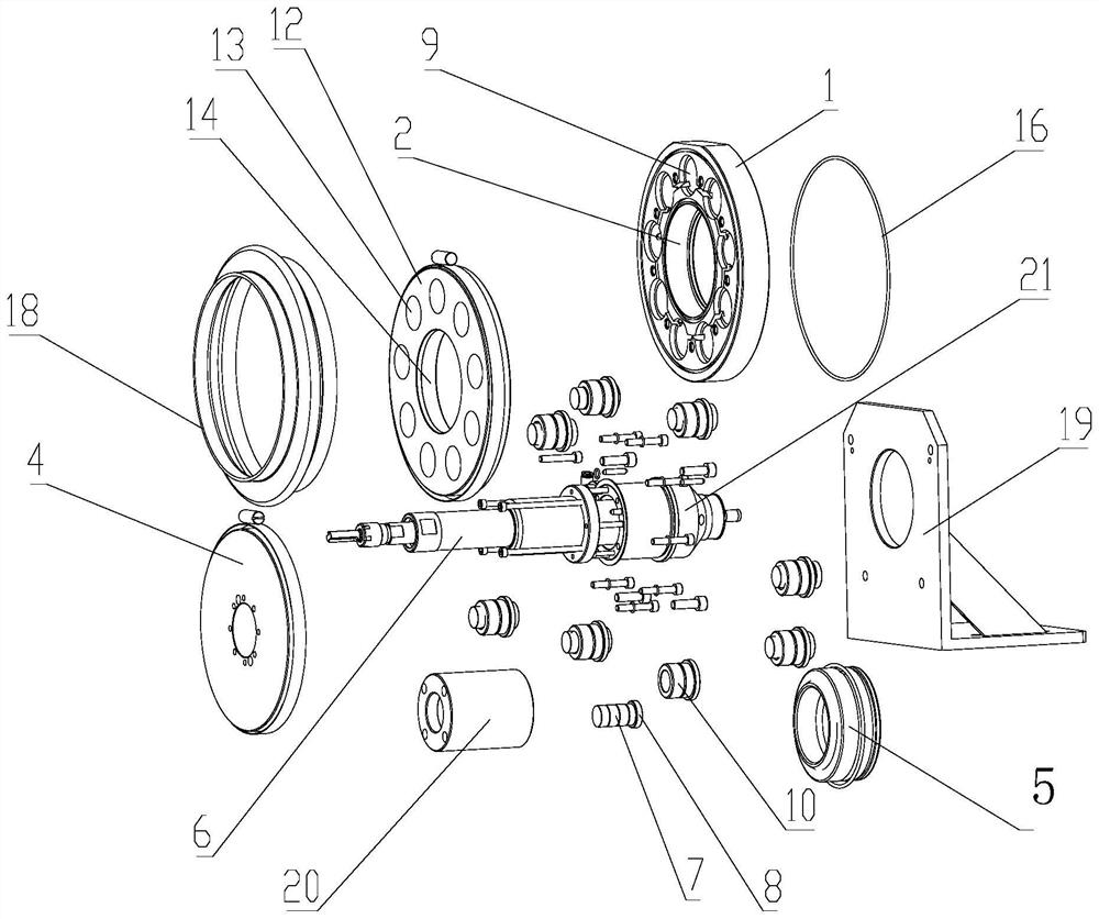
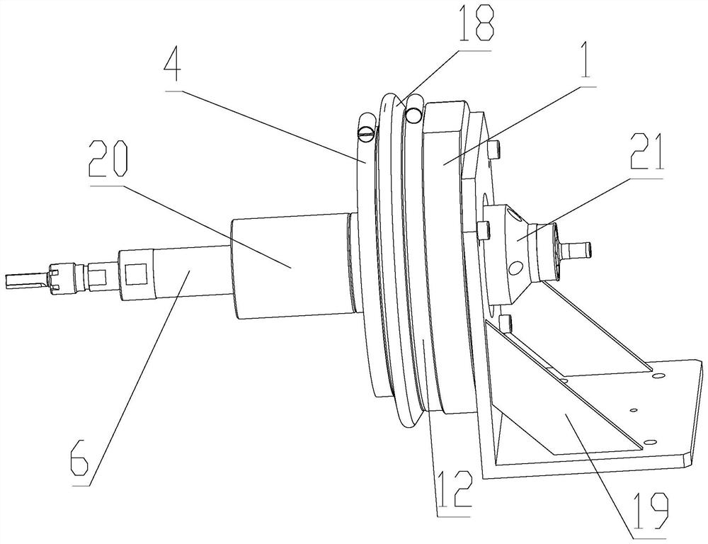
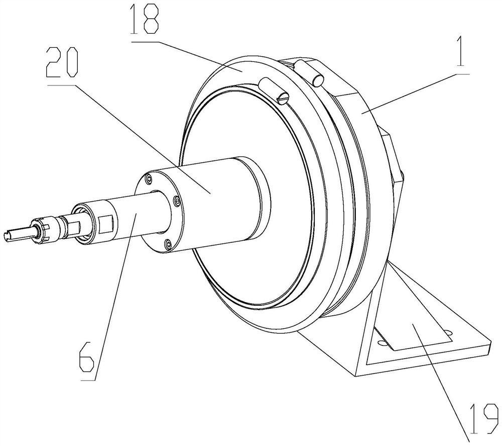
[0025] see Figure 1-6 , a grinding shaft for flexible cleaning of casting blanks, comprising a base plate 1, the base plate 1 is provided with an installation channel 2 that runs through the front and back of the base plate 1, and the base plate 1 is equidistantly arranged around the circumference of the installation channel 2 There are several identical pneumatic telescopic rods, the telescopic direction of the pneumatic telescopic rods faces the front of the base plate 1, and the top ends of all the pneumatic telescopic rods are jointly connected to a floating plate 4 through the first joint bearing 3, and the installation channel 2 is connected between the two ends of the air motor 6 through the second joint bearing 5, the output end of the air motor 6 faces the front of the base plate 1, the air motor 6 runs through the floating plate 4 and the air motor 6 The two ends are fixedly connected to the center of the floating plate 4, and the cylinders of all the pneumatic expa...


PUM


Abstract

The invention belongs to the technical field of grinding assembly manufacturing, and particularly relates to a grinding shaft for flexibly cleaning a casting blank, which comprises a bottom plate, the bottom plate is provided with a mounting channel penetrating through the front surface and the back surface of the bottom plate, and the telescopic direction of a bottom plate telescopic rod faces the front surface of the bottom plate. The top ends of all the pneumatic telescopic rods are jointly connected with a floating plate through first knuckle bearings, the interior of the mounting channel is connected between the two ends of a pneumatic motor through second knuckle bearings, the output end of the pneumatic motor faces the front face of the bottom plate, the pneumatic motor penetrates through the floating plate, and the two ends of the pneumatic motor are fixedly connected with the center of the floating plate. The air cylinders of all the air pressure telescopic rods are communicated in series or in parallel, so that in the deburring process, an output shaft of the pneumatic motor has the function of inclining by a certain angle relative to the surface of a part according to the shape of the surface of the part, and the purpose of completely removing burrs on the surface of the workpiece without damaging the part is achieved.

Description

technical field [0001] The invention belongs to the technical field of grinding assembly manufacturing, in particular to a grinding shaft for flexible cleaning of casting blanks. Background technique [0002] In the process of removing burrs for parts, grinding tools are needed. The existing grinding tools are to install rough grinding cloth or grinding wheel on the rotating shaft, and then drive the rotating shaft to rotate through the motor, thereby driving the grinding cloth or grinding wheel Turn to smooth out burrs. However, when grinding burrs, there is a requirement for the pressure that one end of the grinding cloth or grinding wheel on the rotating shaft contacts the surface of the part. If the pressure of one end of the grinding cloth or grinding wheel contacting the surface of the part is too high, the part will be damaged, and the end of the grinding cloth or grinding wheel will be damaged. If the pressure contacting the surface of the part is too small, the bur...

Claims


Application Information

Patent Timeline
Patent Type & Authority Applications(China)
IPC IPC(8): B24B9/04B24B47/22B24B55/06B24B41/04
Inventor 卢卫根
Owner SUZHOU MINGZHI TECH
Why Eureka
Try Eureka