Hanging rail type inspection robot

An inspection robot and rail-mounted technology, applied in the field of inspection robots, can solve the problems of noise, affecting inspection work, and inconvenient maintenance.

Pending Publication Date: 2022-04-12
HANGZHOU SHENHAO TECH
View PDF11 Cites 2 Cited by
  • Summary
  • Abstract
  • Description
  • Claims
  • Application Information

AI Technical Summary

Problems solved by technology

[0003] Most of the existing inspection robots move in the set track through the drive components, and perform inspections through the camera during the moving process. However, the existing inspection robots have a large contact surface with the track, and generally pass The positioning of the slider is driven by a pulley, so after a long period of use, when the slider is moving, it is likely to generate noise, which affects the normal inspection work, and the existing rail-mounted inspection robot is generally at a higher level. When the camera is damaged, it is inconvenient to overhaul, so we propose a new rail-mounted inspection robot

Method used


Image

  • Hanging rail type inspection robot
  • Hanging rail type inspection robot
  • Hanging rail type inspection robot

Examples


Embodiment 1

[0064] The embodiment of the invention discloses a rail-mounted inspection robot.

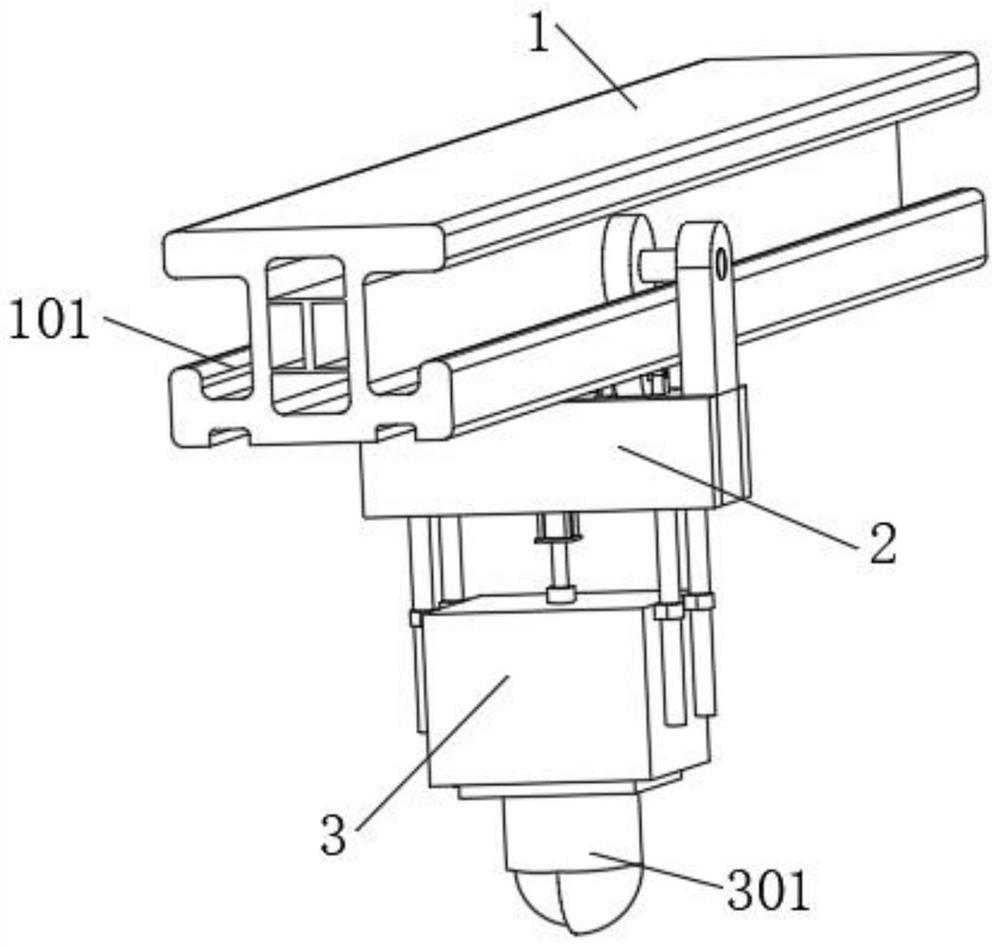
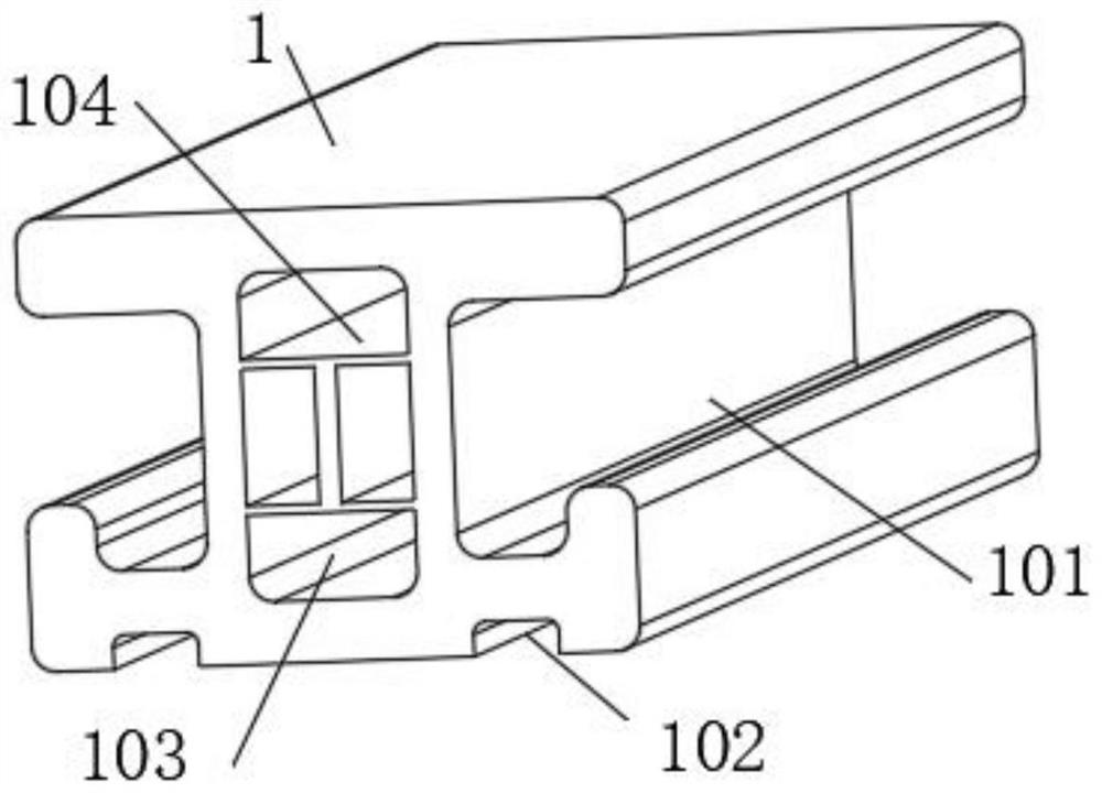
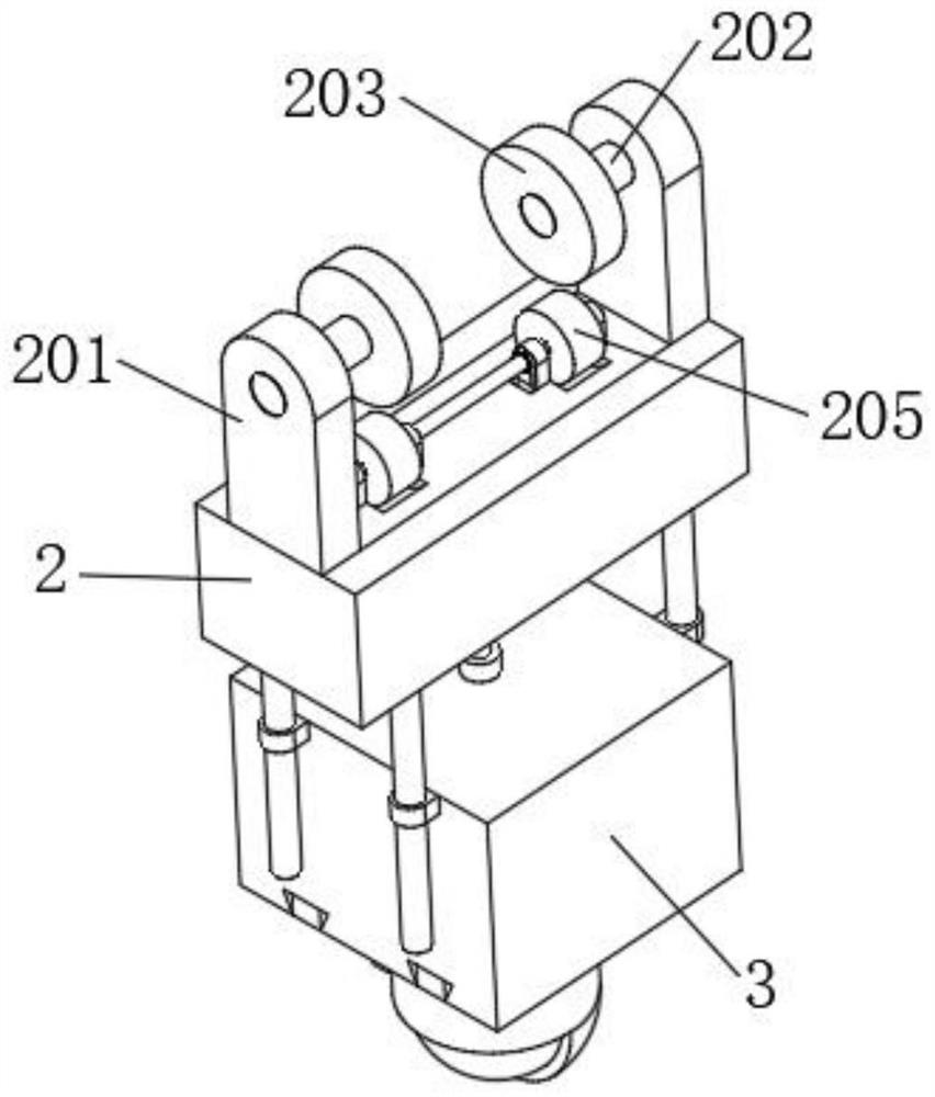
[0065] Please refer to the attached Figure 1-4 ,include:

[0066] The track main body 1 has positioning grooves 101 on both sides of the track main body 1, and two slide grooves 102 are symmetrically opened on the lower surface of the track main body 1;

[0067]The fixed seat 2, the fixed seat 2 is arranged under the track main body 1, and the top of the fixed seat 2 is symmetrically fixedly connected with two support blocks 201, and the opposite sides of the two support blocks 201 are respectively in contact with the two sides of the track main body 1 without squeezing and the tops of the two supporting blocks 201 are fixedly connected with the fixed shaft 202, and the ends of the fixed shaft 202 extend toward the inside of the positioning groove 101, and are fixedly connected with the positioning wheel 203, and the two positioning wheels 203 are respectively connected with the two The inne...

Embodiment 2

[0076] The embodiment of the invention discloses a rail-mounted inspection robot.

[0077] Please refer to attached Figure 1-4 ,include:

[0078] The track main body 1 has positioning grooves 101 on both sides of the track main body 1, and two slide grooves 102 are symmetrically opened on the lower surface of the track main body 1;

[0079] The fixed seat 2, the fixed seat 2 is arranged under the track main body 1, and the top of the fixed seat 2 is symmetrically fixedly connected with two support blocks 201, and the opposite sides of the two support blocks 201 are respectively in contact with the two sides of the track main body 1 without squeezing and the tops of the two supporting blocks 201 are fixedly connected with the fixed shaft 202, and the ends of the fixed shaft 202 extend toward the inside of the positioning groove 101, and are fixedly connected with the positioning wheel 203, and the two positioning wheels 203 are respectively connected with the two The inner b...


PUM


Abstract

The invention relates to a hanging rail type inspection robot, and relates to the field of inspection robots. The rail hanging type inspection robot comprises a rail main body, positioning grooves are formed in the two sides of the rail main body, and two sliding grooves are symmetrically formed in the lower surface of the rail main body; two supporting blocks are symmetrically and fixedly connected to the top of the fixing seat, fixing shafts are fixedly connected to the top ends of the two supporting blocks, positioning wheels are fixedly connected to the ends of the fixing shafts, a rotating rod is rotationally connected to the upper surface of the fixing seat, two driving wheels fixedly sleeve the outer surface of the rotating rod, and a driving assembly is arranged in the fixing seat; a lifting assembly is arranged between the movable seat and the fixed seat, a limiting assembly is arranged at the bottom of the movable seat, and the limiting assembly is connected with an inspection camera. The hanging rail type inspection robot is not prone to generating noise in the moving process, and even if the hanging rail type inspection robot is used for a long time, the situation that noise is generated due to abrasion is avoided.

Description

technical field [0001] The invention relates to the technical field of inspection robots, in particular to a rail-mounted inspection robot. Background technique [0002] With the rapid development of artificial intelligence technology and mobile robot technology, the inspection robot has emerged along with the trend. It can carry a variety of security monitoring equipment to conduct intelligent inspections in the work area, and can make independent decisions and transmit the collected information to the remote surveillance system. [0003] Most of the existing inspection robots move in the set track through the drive components, and perform inspections through the camera during the moving process. However, the existing inspection robots have a large contact surface with the track, and generally pass The positioning of the slider is driven by a pulley, so after a long period of use, when the slider is moving, it is likely to generate noise, which affects the normal inspectio...

Claims


Application Information

Patent Timeline
Patent Type & Authority Applications(China)
IPC IPC(8): B25J11/00B25J5/02B25J19/02
Inventor 吴利军邓成呈丁祥宇汪春
Owner HANGZHOU SHENHAO TECH
Why Eureka
Try Eureka