Material moving mechanism applied to automatic assembly line

A material-moving mechanism and assembly line technology, which is applied in the direction of conveyor objects, transportation and packaging, chute, etc., to avoid mechanical impact.

Inactive Publication Date: 2022-04-12
安徽洪雷工业技术有限公司
View PDF1 Cites 0 Cited by
  • Summary
  • Abstract
  • Description
  • Claims
  • Application Information

AI Technical Summary

Problems solved by technology

[0006] The object of the present invention is to provide a material-shifting mechanism applied to the automatic assembly line. By setting the material-moving mechanism on the automatic assembly line, the materi

Method used


Image

  • Material moving mechanism applied to automatic assembly line
  • Material moving mechanism applied to automatic assembly line
  • Material moving mechanism applied to automatic assembly line

Examples


Embodiment 1

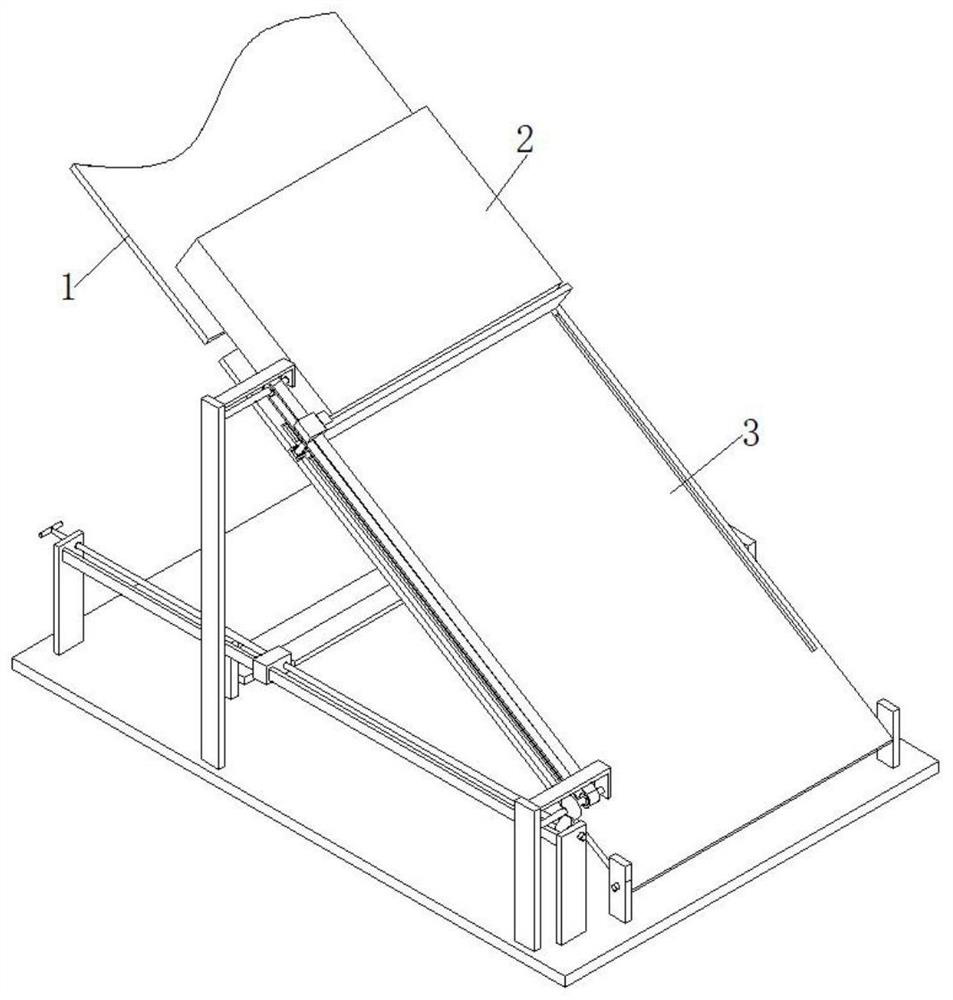
[0032] see figure 1 As shown, the present invention is a material shifting mechanism applied to an automated assembly line, including an automated assembly line, an inclined plate 1 and a workpiece 2 are included on the automated assembly line, a material transfer mechanism 3 is arranged on the automated assembly line, and the material transfer mechanism 3 is located on an inclined At one end of the plate 1, the material shifting mechanism 3 cooperates with the inclined plate 1 to realize the movement of the workpiece 2 from top to bottom.

Embodiment 2

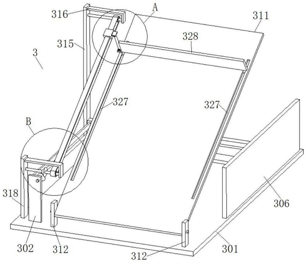
[0034] Based on the technical solution described in the first embodiment above. see Figure 2-6 As shown, the material transfer mechanism 3 includes a machine platform 301 , a connecting push rod 310 , a movable plate 311 , a sliding plate 328 and a telescopic rod 332 . The upper surface of the machine table 301 is provided with a pair of first vertical support plates 302, a horizontal sliding plate 303 is fixedly connected between the pair of first vertical support plates 302, and a horizontal sliding plate 303 is rotatably connected between the pair of first vertical support plates 302. Screw mandrel 304. A first slide block 305 is slidably installed on the transverse slide plate 303, and a threaded hole is provided on the first slide block 305, and the transverse screw rod 304 is meshed with the threaded hole on the first slide block 305, and the transverse screw rod 304 drives the first slide block 305 slides on the horizontal slide plate 303.

[0035] The upper surface...

Embodiment 3

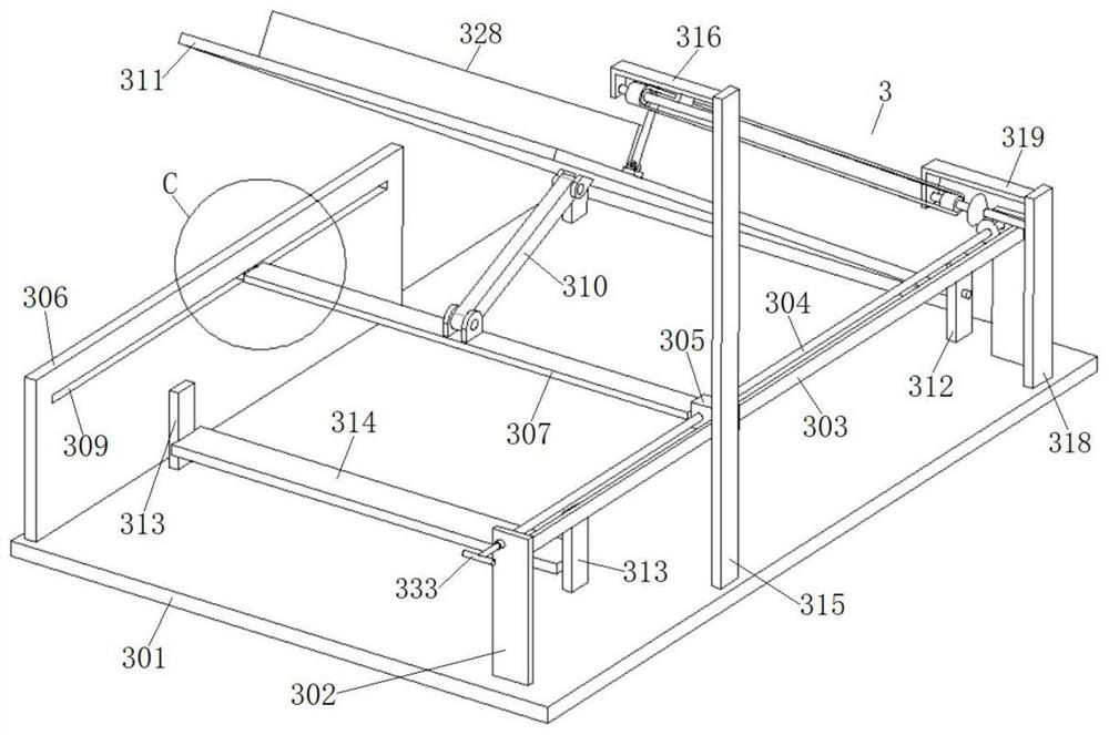
[0042] Based on the technical solution described in the second embodiment above. see image 3 As shown, an elastic pad can be provided on the transverse support plate 314, so that the movable plate 311 is turned from an inclined state to a horizontal state and rests on the elastic pad, so as to avoid mechanical impact on the movable plate 311. One end of the horizontal screw rod 304 is provided with a handle bar 333, the handle bar 333 is a T-shaped structure, by rotating the handle bar 333, the upper surface of the movable plate 311 is coplanar with the upper surface of the inclined plate 1, so that the workpiece 2 can move smoothly from the inclined plate 1 slide onto the movable plate 311.


PUM


Abstract

The invention discloses a material moving mechanism applied to an automatic assembly line, and relates to the technical field of automatic equipment. Comprising an automatic assembly line, the automatic assembly line comprises an inclined plate and a workpiece, the automatic assembly line is provided with a material moving mechanism, the material moving mechanism is located at one end of the inclined plate, and the material moving mechanism and the inclined plate are matched to achieve movement of the workpiece from top to bottom; the other end of the connecting ejector rod is hinged to the middle of the back of the movable plate. A workpiece moves downwards from the inclined plate to the movable plate, the workpiece is converted into a horizontal state from an inclined state in the downward moving process under the action of the material moving mechanism, the workpiece stably moves from top to bottom, and mechanical impact on the workpiece is avoided.

Description

technical field [0001] The invention belongs to the technical field of automation equipment, and in particular relates to a material shifting mechanism applied to an automatic assembly line. Background technique [0002] With the vigorous promotion and large-scale popularization of automation technology in the field of industrial manufacturing, all aspects of the entire manufacturing field have gradually realized the situation of modern manufacturing such as automation and semi-automation. In the first-line production assembly, the seamless connection between automation and intelligent equipment is realized between the stations, which liberates and separates human hands from the first-line production line. [0003] In the existing automatic assembly line, there is usually a need to move a workpiece from a high place to a low place, and directly drop the workpiece from a high place to a low place, there will be a certain mechanical impact, which is easy to damage the workpiec...

Claims


Application Information

Patent Timeline
IPC IPC(8): B65G11/20B65G47/96
Inventor 雷亮亮雷振友
Owner 安徽洪雷工业技术有限公司
Why Eureka
Try Eureka