Washing machine

A washing machine and air intake channel technology, applied in the field of washing machines, can solve the problems of single water flow, wear, and entanglement of clothes, and achieve the effects of alleviating entanglement of clothes and serious wear and tear of clothes, reducing design and manufacturing costs, and reducing production costs.

Pending Publication Date: 2022-04-12
QINGDAO HAIER WASHING MASCH CO LTD +1
View PDF0 Cites 0 Cited by
  • Summary
  • Abstract
  • Description
  • Claims
  • Application Information

AI Technical Summary

Problems solved by technology

The current washing method of the washing machine forms a ring-shaped washing water flow in the inner tub, the water flow form is single, and the washing effect is average, and the washing water flow formed by driving the washing water only through the pulsator is easy to entangle the clothes and cause serious wear and tear.
[0003] In order to solve the above problems, those skilled in the art have developed a washing machine that uses an air supply device to feed air into the inner tub to form a surging washing water flow in the inner tub to solve the problems of entanglement and serious wear of clothes. However, it provides In washing machines, the air intake channel of the air supply device needs to pass through the drive device installed on the bottom wall of the outer tub to communicate with the interior of the inner tub. In order to meet the different orientation requirements of the air intake channel, the structure of the drive device also needs to be adapted. , so that the versatility of the driving device is low, and the driving device of various structural types also increases its own design and manufacturing costs, thereby increasing the production cost of the washing machine

Method used


Image

  • Washing machine
  • Washing machine
  • Washing machine

Examples


Embodiment approach

[0077] Specifically, the structure of the washing machine provided in this example is introduced in detail through the following two implementation modes:

[0078] The first implementation mode:

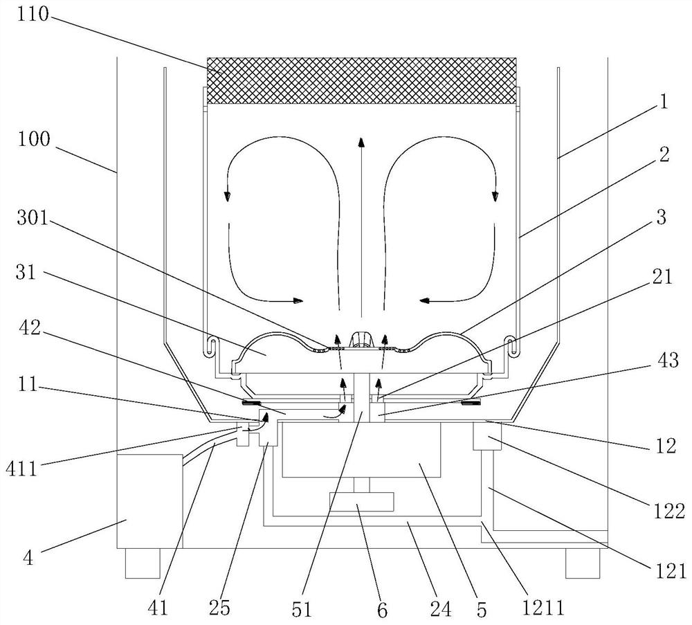
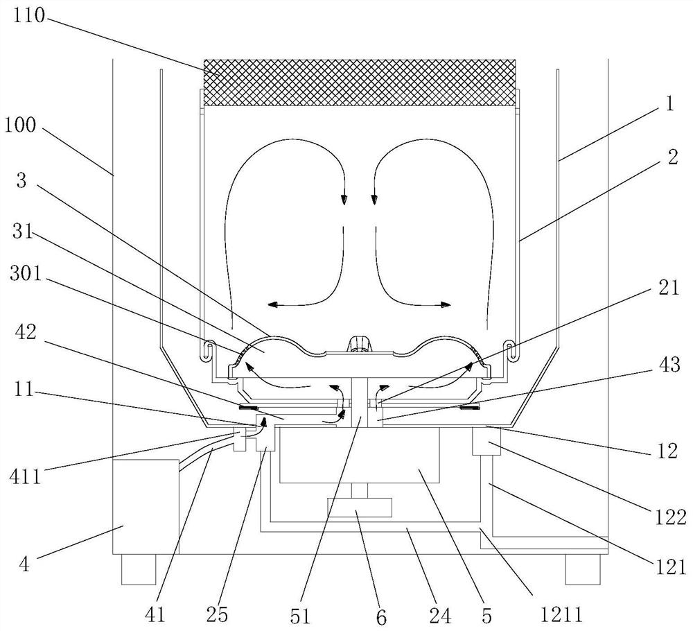
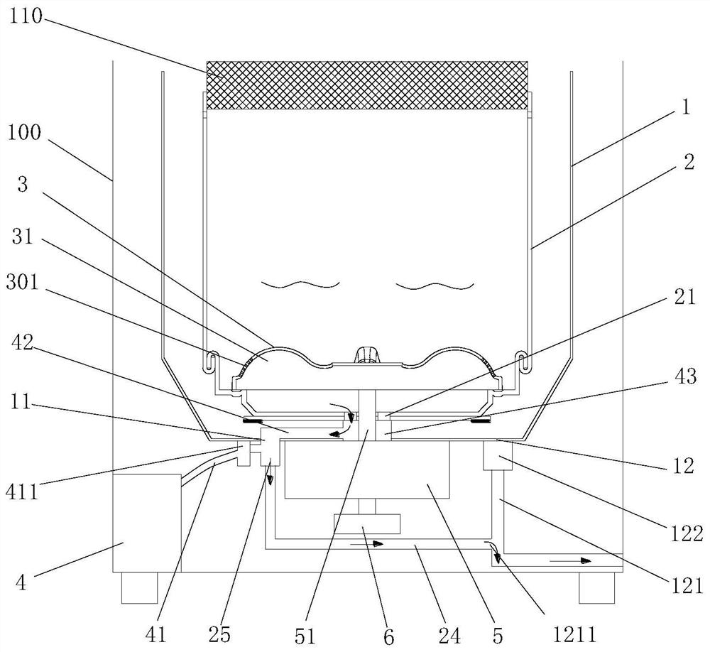
[0079] This embodiment mainly introduces that the inlet end of the second air intake passage 42 is connected to the first air intake passage 41 through the conduction port 11 , so as to realize the communication between the air supply device 4 and the inner tub 2 .

[0080] Specifically, a first connection port is opened on the peripheral side wall of the annular communication part, and the second air intake passage 42 includes a first horizontal pipe arranged between the first connection port and the conduction port 11 , The first horizontal pipe is located inside the tub 1, one end of the first horizontal pipe is connected to the first connection port and the other end extends vertically downward to form a first vertical pipe; the first vertical pipe is formed by the The conductio...


PUM


Abstract

A washing machine includes: an inner tub; the outer barrel is coaxially arranged outside the inner barrel; the driving device is mounted on the outer side of the bottom wall of the outer barrel and is in driving connection with the inner barrel; the air supply device is arranged outside the outer barrel, air is fed into the inner barrel through an air inlet channel, and surging washing water flow is formed in the inner barrel; along the direction of the central axis of the outer barrel, the area covered by the projection of the driving device on the bottom wall of the outer barrel is a first area, the bottom wall of the outer barrel located outside the first area is provided with a communicating opening, and the air inlet channel can penetrate through the communicating opening or be connected to the communicating opening to achieve communication with the interior of the inner barrel. According to the washing machine, the phenomenon that clothes are wound and abraded seriously in a traditional washing mode is relieved, the clothes washing effect is improved, the air inlet channel is located outside the driving device through the communicating opening formed in the bottom wall of the outer barrel outside the first area, the problem that the air inlet channel interferes with the driving device is effectively solved, and the service life of the air inlet channel is prolonged. And the universality of the driving device is improved.

Description

technical field [0001] The invention belongs to the field of clothes processing devices, and in particular relates to a washing machine. Background technique [0002] Existing pulsator washing machine, washing principle is developed by imitating people's manual rubbing of clothes, and the main part that produces mechanical action is the pulsator, which is positioned at the bottom of the barrel of the inner barrel. The washing machine controls the washing machine motor through the computer program controller to intermittently perform positive and negative rotation according to the set rotation ratio, forming a vortex water flow to wash the clothes. However, this kind of water flow is faster on the outside of the pulsator, and slower on the inside. With the water flow, the clothes are constantly rotating, tumbling, and constantly squeezed to the center, resulting in entanglement. The existing washing method of the washing machine forms a ring-shaped washing water flow in the ...

Claims


Application Information

Patent Timeline
Patent Type & Authority Applications(China)
IPC IPC(8): D06F37/00D06F39/08
CPCY02B40/00
Inventor 宋秀顺刘尊安庄仲凯李新亮
Owner QINGDAO HAIER WASHING MASCH CO LTD
Why Eureka
Try Eureka