Transformer winding compaction force detection system and detection method

A transformer winding and detection system technology, applied in the direction of force/torque/power measuring instruments, instruments, measuring devices, etc., can solve the problems of winding detection error, uniform force, and inability to provide winding, so as to reduce test error and facilitate Pressure detection, easy detection effect

Pending Publication Date: 2022-04-12
GUANGXI POWER GRID CO LTD NANNING POWER SUPPLY BUREAU +1
View PDF1 Cites 0 Cited by
  • Summary
  • Abstract
  • Description
  • Claims
  • Application Information

AI Technical Summary

Problems solved by technology

[0003] In the prior art, the patent whose application number is CN201920360917.0 discloses a multi-range pressure sensor and a pressure controller with it, including a first pressure sensor, a second pressure sensor and a third pressure sensor arranged in series in sequence ; There is a deformation gap between the first pressure sensor and the second pressure sensor and the second pressure sensor and the third pressure sensor; the first pressure sensor, the second pressure sensor and the third pressure sensor The pressure detection results of the pressure sensors are respectively connected to the pressure transmission circuit, and the pressure transmission circuit is connected to the pressure receiving circuit; the measurement range of the first pressure sensor is smaller than the measurement range of the second pressure sensor, and the measurement range of the second pressure sensor The measurement range of the third pressure sensor is smaller than the measurement range of the third pressure sensor. Although the above-mentioned utility model has the advantages of simple structure, low cost, high test accuracy, wide application range, and wide application prospects, the method of using the pressure sensor to detect the transformer winding At this time, it is impossible to provide a uniform force on the winding, which leads to the disadvantage of errors in the winding detection process. Therefore, a transformer winding compaction force detection system and detection method are proposed.

Method used


Image

  • Transformer winding compaction force detection system and detection method
  • Transformer winding compaction force detection system and detection method
  • Transformer winding compaction force detection system and detection method

Examples


Embodiment Construction

[0025] The following will clearly and completely describe the technical solutions in the embodiments of the present invention with reference to the accompanying drawings in the embodiments of the present invention. Obviously, the described embodiments are only some, not all, embodiments of the present invention. Based on the embodiments of the present invention, all other embodiments obtained by persons of ordinary skill in the art without making creative efforts belong to the protection scope of the present invention.

[0026] In addition, an element in the present invention is said to be "fixed" or "disposed on" another element, and it may be directly on another element or an intervening element may also exist. When an element is referred to as being "connected to" another element, it can be directly connected to the other element or intervening elements may also be present. The terms "vertical," "horizontal," "left," "right," and similar expressions are used herein for purp...


PUM


Abstract

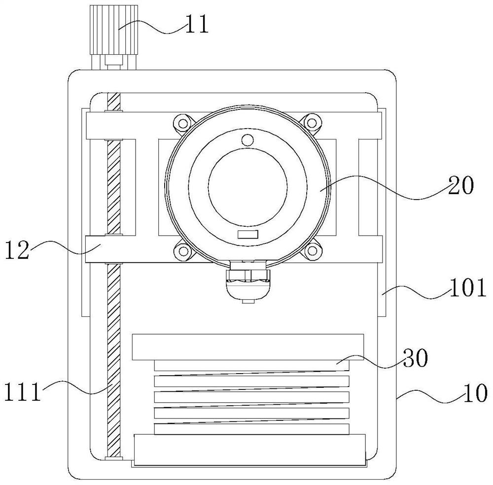
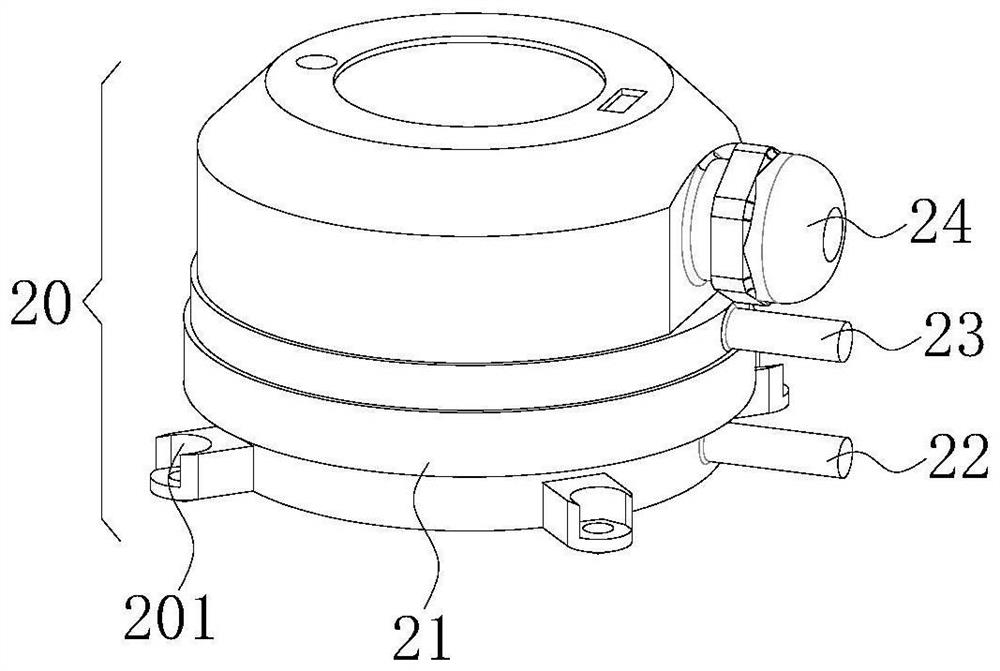
The invention provides a transformer winding compaction force detection system and detection method, and belongs to the technical field of transformer detection, the transformer winding compaction force detection system comprises a frame body and a detector body, a winding is placed in the frame body, the top end of the frame body is fixedly connected with a driving motor, the output end of the driving motor is fixedly connected with a second threaded rod, and the second threaded rod is fixedly connected with a first threaded rod. The second threaded rod extends into the frame body and is rotationally connected with the frame body, two first sliding grooves are formed in the inner side wall of the frame body, the two first sliding grooves are located in the two sides of the interior of the frame body correspondingly, and through arrangement of the first sliding blocks and the second threaded rod, the second threaded rod is driven by a driving motor to rotate; when the threaded rod rotates, the detector body can be further controlled to slide in the frame body, and the detector body provides a uniform pushing force for the winding in the sliding process, so that the detection error caused by non-uniform pushing force when the detector body performs pressure detection on the winding is reduced.

Description

technical field [0001] The invention relates to the technical field of transformer detection, in particular to a detection system and detection method for the compaction force of a transformer winding. Background technique [0002] A transformer is a device that uses the principle of electromagnetic induction to change the AC voltage. Its main components are primary coils, secondary coils, windings and iron cores. In order to form a closed state, the iron cores used in three-phase transformers often need to pass through multiple The iron core is composed of silicon steel sheets pressed together, and the winding is sleeved on the iron core after synthesis. [0003] In the prior art, the patent whose application number is CN201920360917.0 discloses a multi-range pressure sensor and a pressure controller with it, including a first pressure sensor, a second pressure sensor and a third pressure sensor arranged in series in sequence ; There is a deformation gap between the first ...

Claims


Application Information

Patent Timeline
Patent Type & Authority Applications(China)
IPC IPC(8): G01L5/00G01B11/14
Inventor 覃智贤贾雅君于树海罗传胜苏颜周闯廖英怀伍任能桂路陈斌徐兆丹肖远平杨长森李宝峰何位经廖钊方番罗喜宋喜平孙全才李宏士
Owner GUANGXI POWER GRID CO LTD NANNING POWER SUPPLY BUREAU
Why Eureka
Try Eureka